Week 9 - Challenge 1 - Base Bracket Design
AIM : To Create the Base Bracket Plastic component through the given Class-A surface. To begin with, the tooling axis for the given Class-A Surface should be created meeting the requirements of the draft angle and at the end perform the Draft analysis on the model.
Given Class A Surface
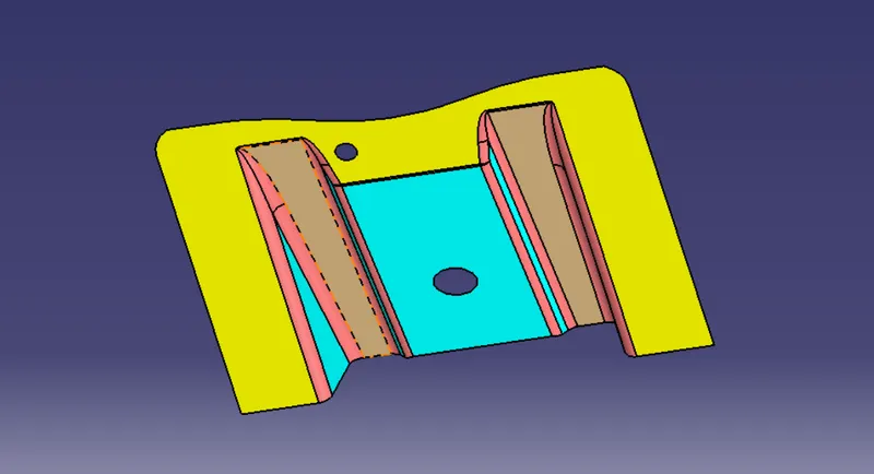
STEP 1: Check the connectivity of the Class A Surface .Ensure that there is no gap between the component, using the join command. We can visually check it or by clicking the boundary command.
STEP 2: Find the tooling axis of the component.
STEP 3 : Now creating Class B Surface By offset it to 2.5mm .Now use Join command to see whether surface discontinuities are there or not . Now,' Extrapolate' the Class B surface
STEP4 : Create Class C surface by using Sweep Command using 'Draft direction' as Tooling axis
STEP5: Join the ' Class A ' Surface and the ' Class C ' surface .
STEP6: Now Trim the (A+C) Surface with the Class B surface to get Final Part
STEP7: Use either "Thicken Command " or " Close Surface " Command to Convert it into Solid body
- An explanation should be given on the way of creating the tooling axis, particularly the Bisecting method
Creation of Tooling Axis
- Tooling axis is the direction in which the core and cavity opens. It is basically the direction that the mold pulls apart. Creating a tooling axis is necessary to provide draft angle and analyze them. The tooling axis is created using Bisecting method and by visually checking too .
- The tooling axis is nothing but the mold opens or the cavity opens. To know the Tooling Axis ,First Start Working on Holes and large Flat Surface on the Given Class A surface.
- Initially ,Check visually which is the best possible tooling axis .
Check all three axes.
Along X ,it is possible but expensive and Y is not possible.
Hence , Z is the Only best possible Tooling axis . Moreover Along Z axis the whole part is clearlly Visible compared to X and Y axes
Creating a Tooling axis along Z Direction :
To decide the Tooling axis, it is made sure that the component is clearing the tooling axis in the given specific direction. The first step is to visually check the component for the best tooling direction in all three x, y and z directions. In the given Class A surface it is found that the best tooling direction is Z axis as the holes present on the surface cannot be cleared in either X or Y directions with minimum tooling. So Z direction is chosen for Tooling axis.
After the selection of direction, a dummy tooling axis is created in that direction for reference.
- Take a Point Over Hole surface present on Class A surface . Now Draw a Line along Z direction through ' Point to direction ' Method . The Line drawn is our Required Dummy Tooling Axis .
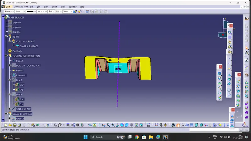
Bisecting Method
- First , Create a Plane Using the Point that is created already over Hole on Class A surface for creation of Dummy Tooling Axis and Use YZ plane as reference
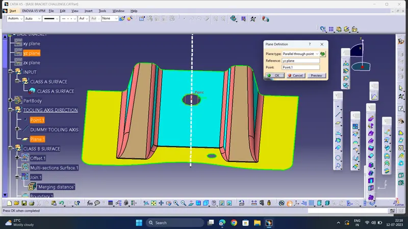
- Now using " Intersection " Command intersect the Class A surface With the YZ plane
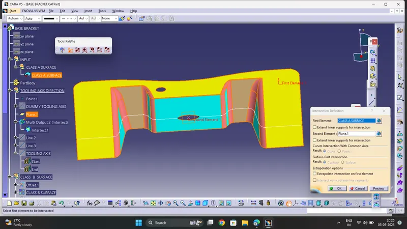
- Now draw two lines on either sides of Intersection Curve of Class A surface with the YZ Plane using ' Point to Point ' Method as shown
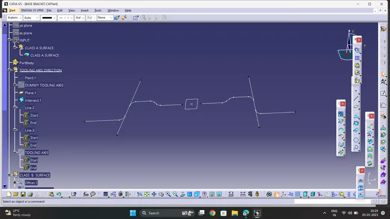
- Now Create another Line Using Bisecting Line Method through Two Lines and a Point as shown
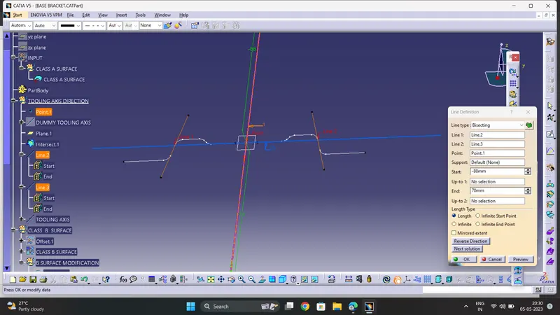
- The Obtained Bisecting Line is Our Required Main Tooling Axis . If you Compare both Dummy Tooling Axis and the Main Tooling Axis ,both are Same and coincide . Hence both the methods are Followed
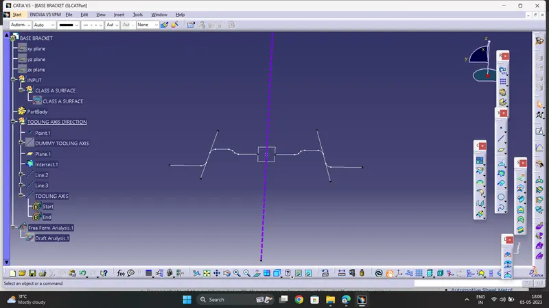
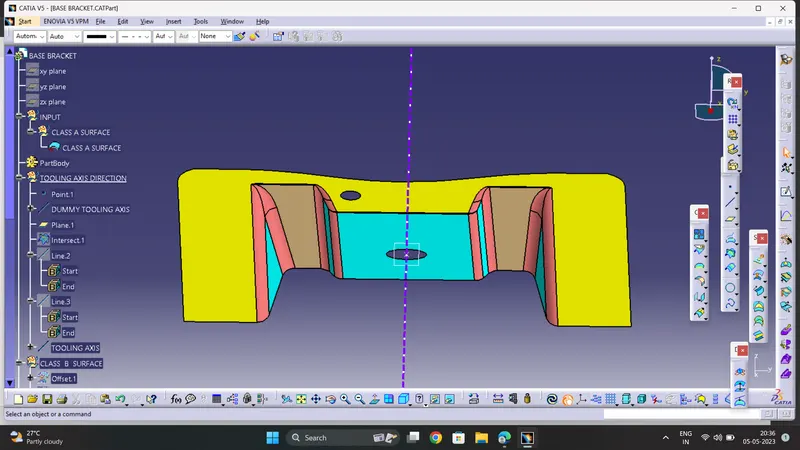
- A detailed report should be done explaining the draft analysis
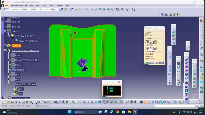
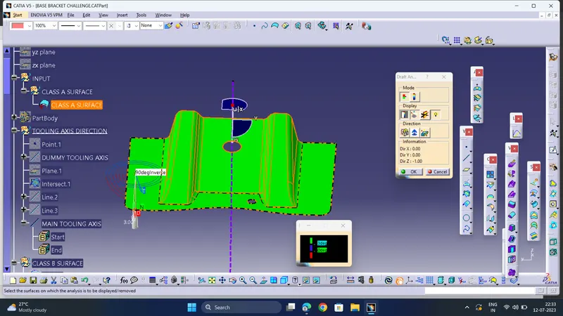
Draft Analysis
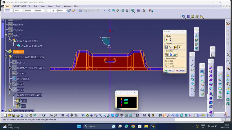
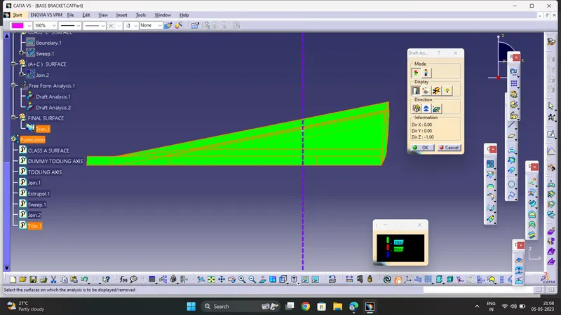
- Follow the steps : Insert--->Analysis----->Feature Draft Analysis
- Place the Compass on the Tooling Axis and Lock it
- Click on the surface of the part to see the minimum Draft angles on the part
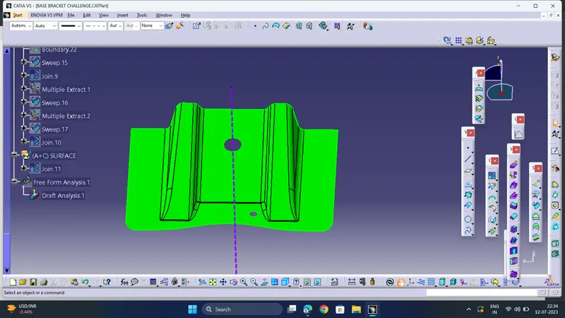
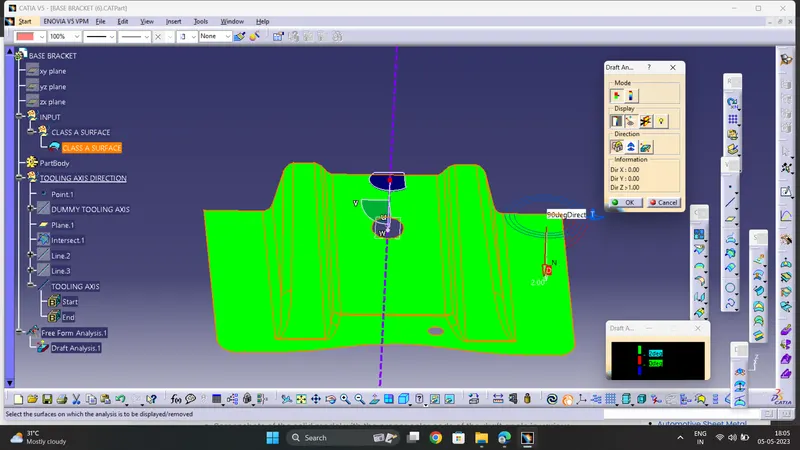
1)Draft Analysis on Class A surface :
2)Draft Analysis on Final Part
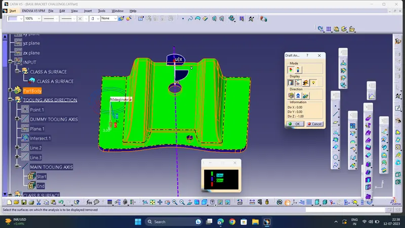
- Screenshots of the Draft analysis report for both the given Class-A surface and the final plastic component
Class A Surface
Final Part
- Images of the color scale variant
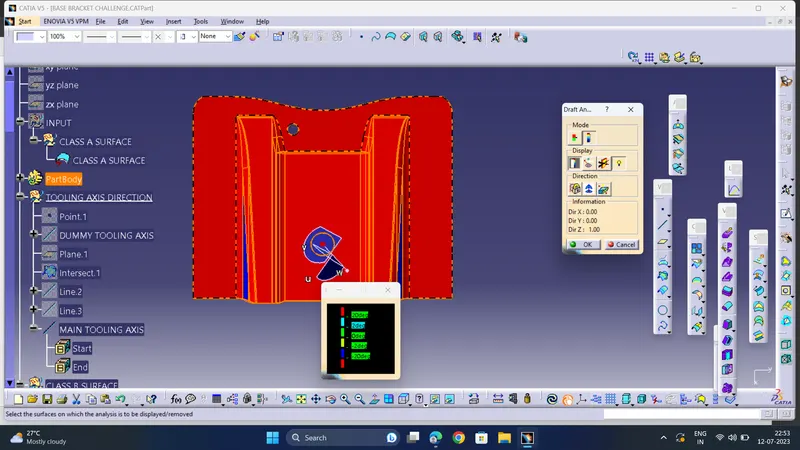
- Image of the complete Draft analysis
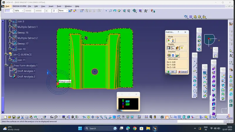
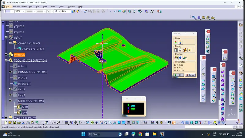
- Screenshots of the solid model with the proper color code of the draft angle in various orientations (Isometric, Front, Side, and Top View)
ISOMETRIC VIEW
FRONT VIEW
SIDE VIEW
TOP VIEW