Week 9 - Challenge 1 - Base Bracket Design
BASE BRACKET:
Aim;
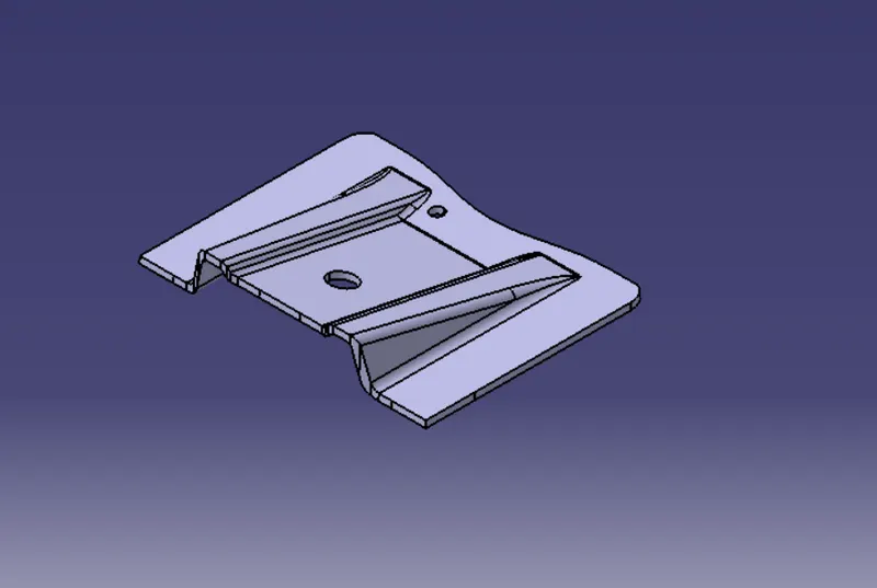
Design the base bracket with the closed surface by the given Class-A surface and then create the base bracket solid plastic component.
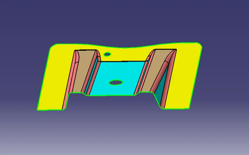
Design Procedure;
- Create a tooling axis on a Class-A surface.
- To verify draft analysis.
- To create a B surface & C surface.
- To create a trimmed surface.
- To create a solid model part.
Tooling Axis;
To check the conectivity of the surfaces using boundaries.
To create a point, then the dummy tooling axis is created directly using point-direction command.
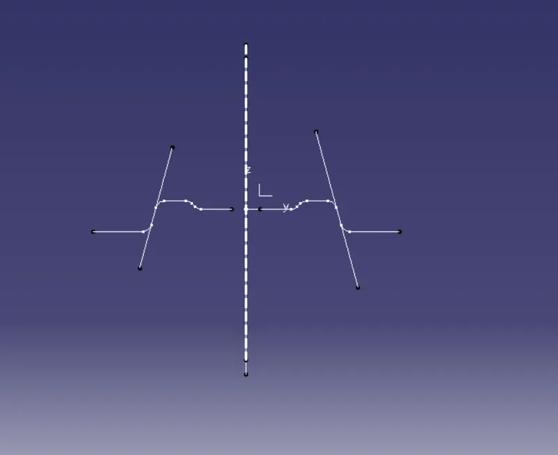
The clearance checking along all the axis direction will be done by creating an intersection along an axis on a plane with the model and constructing two lines contact with the walls, the line bisecting the two lines and passing through the point will be the tooling axis.
Using the tooling axis created along x and y-axis, these tooling axes are used for creation of tooling axis by bisecting method where the two lines and point will be selected as inputs.
Draft Analysis;
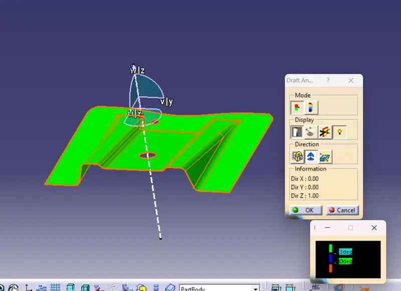
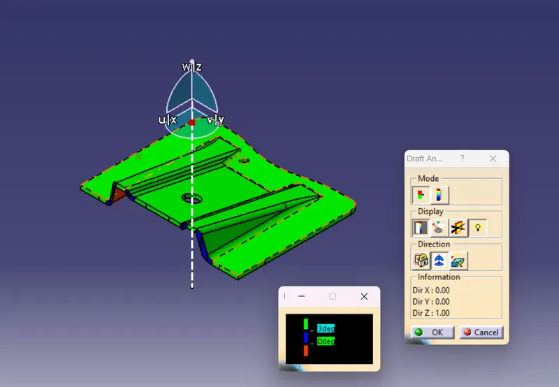
Draft analysis is donr after determining the tooling axis on the Class-A surface, Draft analysis is used on the Class-A surface to check whether the minimum draft angle 3 degrees is maintained or not.
Given a surface angle of minimum 3 degerees, the whole component truns green. If the component truns green, we go to next operation.
Class-B Surface;
The Class-B surface is the secondary surface in the plastic component.
Class B-Surface is extracted from the A-surface and it is offseted at 2.5mm in downward direction.
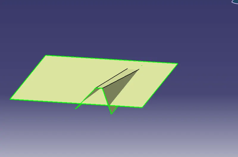
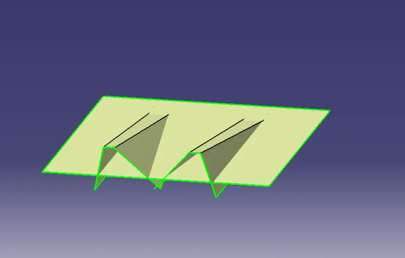
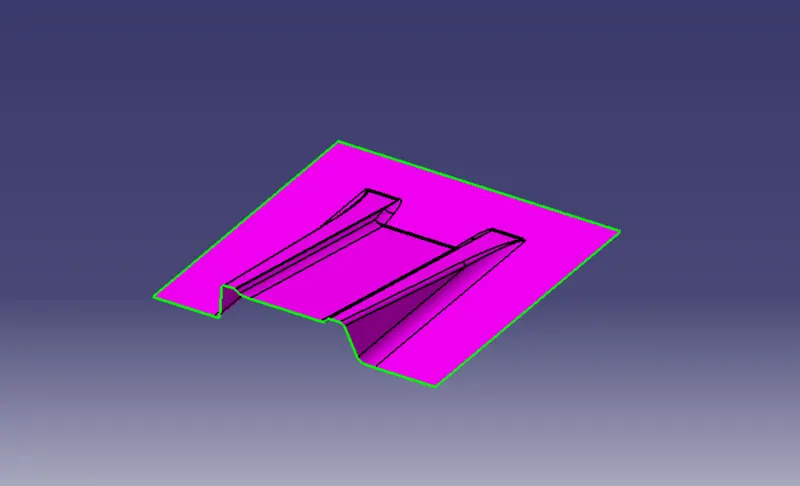
The Class-B surface for the base bracket is designed to step by step by creating the rib-1,rib-2 and then creating the base surface.
First the rib surface is extracted using the extract command from Class-A surface, then the untrimmed commmand is used to the extracted surface. Then the untrimmed surface was extended by using extrapolate command for getting better interference between the surface. The surface was then offset again 2.5mm and then the required area was attached using the trim command.
Class-C surface;
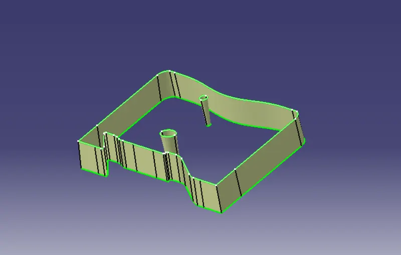
Class C surface is the surface that joins the Class A & B surfaces together.
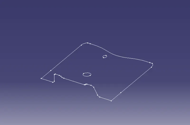
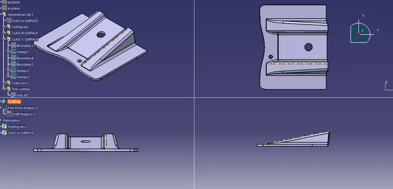
The outer boundary of the Class A surface is extracted and then the Class C surface created using the swept surface tool with help of the downward direction of the tooling axis,Then by following the same method the two holes were generated and joined together to form a complete surface with no gaps, then joint the Class A & C surface using joint command.
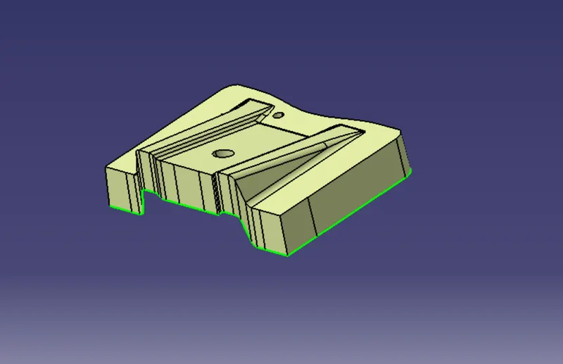
Trimmed surface;
Class A & B surfaces created using the trim command are joined to the required Class C surface. Finally got a trimmed surface.
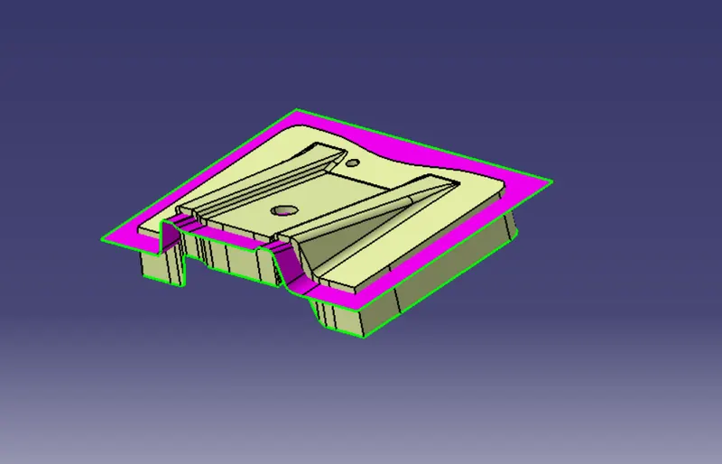
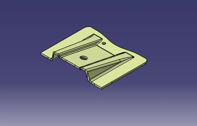
Then the final trimmed surface was also checked for the draft analysis for satisfying the manufacturing requirement.
Solid Part;
A solid part is created using the closed surface command on a trimmed surface.
Conclusion;
The Design of Plastic Component - Base Bracket from Class A is completed using concepts of Draft angle, Draft Analysis, Tooling Axis, Class B and Class C creation and converting Closed surface to a solid part.