Week 9 - Challenge 1 - Base Bracket Design
Aim:
To construct a Base Bracket Plastic Component from a specified Class A Surface and perform Draft Analysis on the resulting plastic component.
Objectives:
- To create a tooling axis.
- Surfaces of Class B and Class C are created.
- Making a solid component from a surface model.
- Draft analysis of Class A surface and finished plastic component.
- CATIA V5 was used as a tool.
METHODOLOGY:
- We have focused on the following things in this model:
- Tooling axis
- Draft analysis
- Class-B surface
- Class-C surface
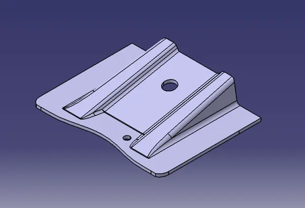
- Making a solid model from surface.
- To complete the task, the following things were used:
- Extract
- Un-trim
- Trim
- Extrapolate
- Offset
- Edge fillet
- Boundary
- Sweep
- Join
- Close (part design)
Introduction:
In this project, we will create a base bracket from a provided class A surface. The technique entails creating a Class B surface with a thickness of 3 mm for the whole component. The design also featured the generation of a Class C surface from the specified parent surface.
CLASS A:
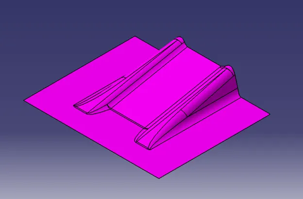
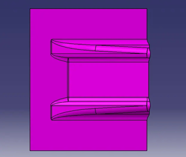
The following surface is used as the component's input.
To proceed with the design process, we must first determine the tooling axis for the surface and verify for all draft using CATIA's Draft Analysis tool.
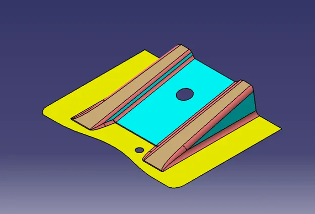
Surface A Draft Analysis:
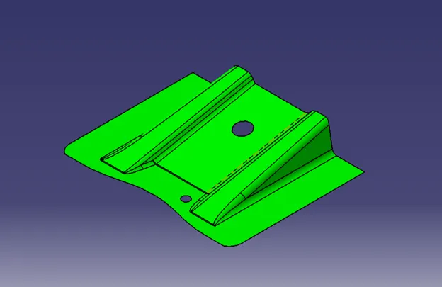
The analysis is performed for a 3 degree Draft. As can be observed, all of the surfaces are more than 3 degrees.
Tooling Axis Creation:
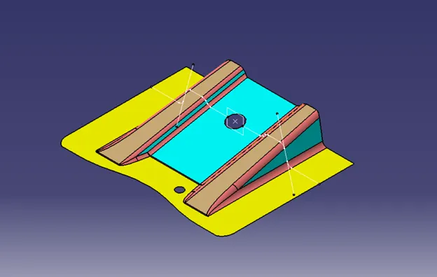
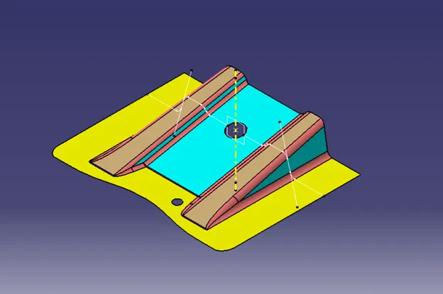
Make an intersection of the CLASS A surface and the ZX plane, and then establish the tooling axis as illustrated below.
Class B creation:
- For Class B creation, we removed the surface from Class A and untrimmed it to recover the original parent surface.
- The thickness of these surfaces is then offset.
- Following offsetting, all surfaces are cut to the desired form.
- Surfaces are given the necessary fillets.
Class C creation:
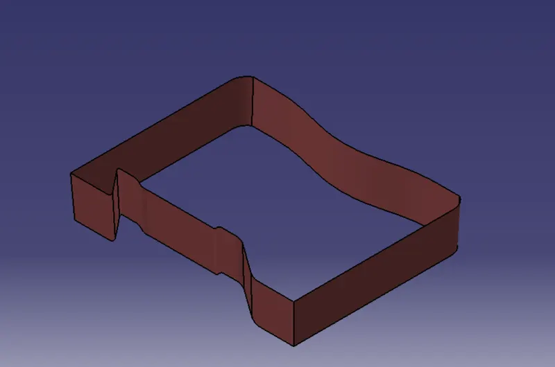
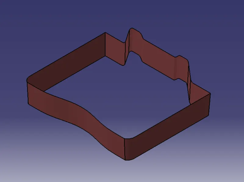
- Class C was created by extracting the boundry of Class A with multi-extract and then converting it to a smooth curve.
- This smooth curve is now swept with a 3° draft along the Draft direction.
Final trims:
- Classes A and C:
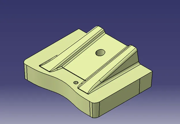
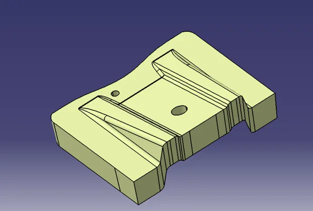
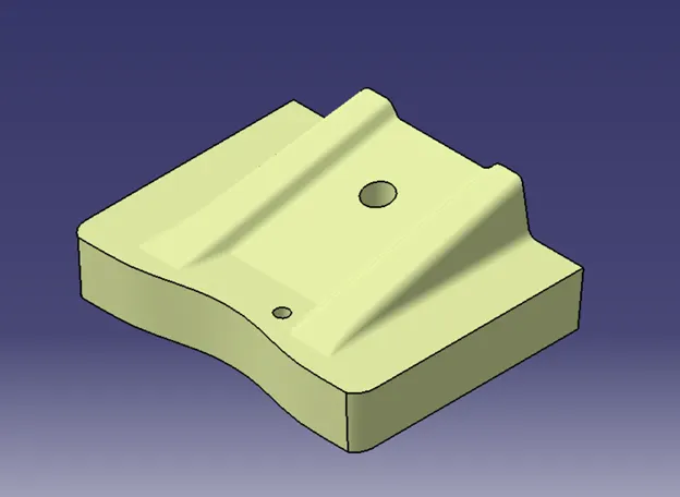
We utilised the join option to form the single body to ensure that there are no open boundaries between classes A and C. This is done to ensure that the separating line does not fall between these two surfaces.
- Classes A, B, and C together:
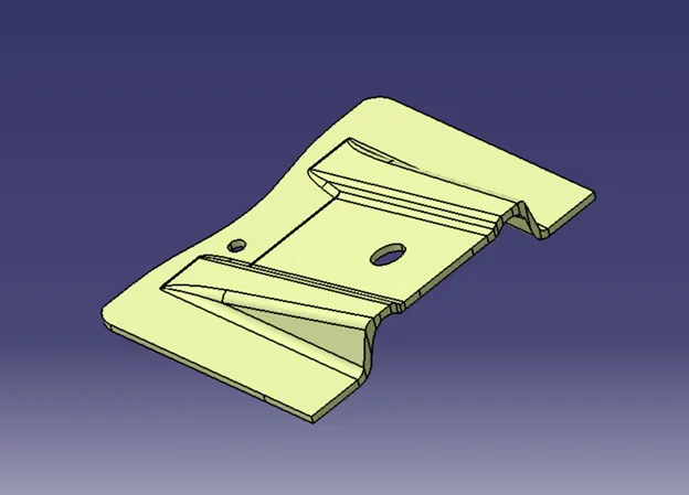
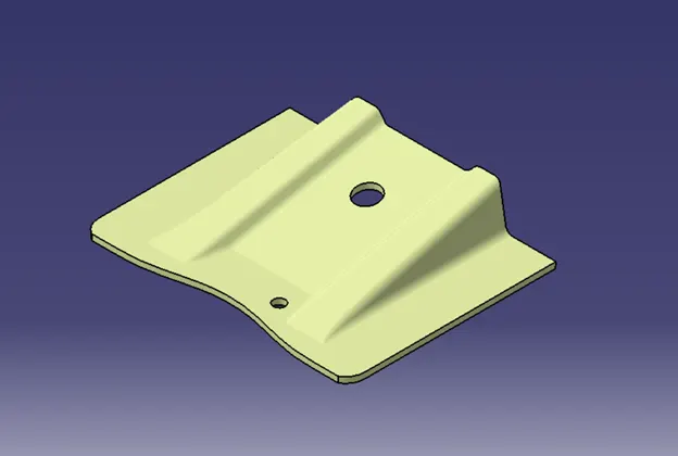
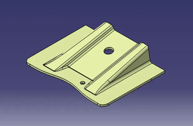
We used the trim option to trim the surface to the Class B surface.
Solid Body:
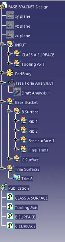
Tree Structure:
Conclusion:
All the given drawings and modelling are done as per requirements.