Week 9 - Challenge 1 - Base Bracket Design
OBJECTIVE:
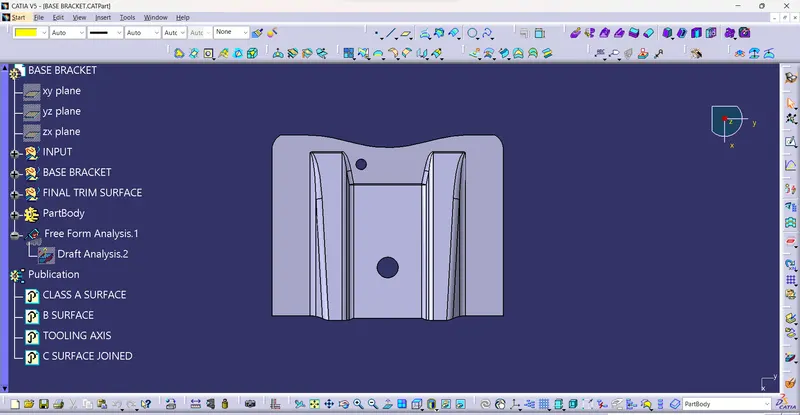
Create the Base Bracket Plastic component through the given Class-A surface.
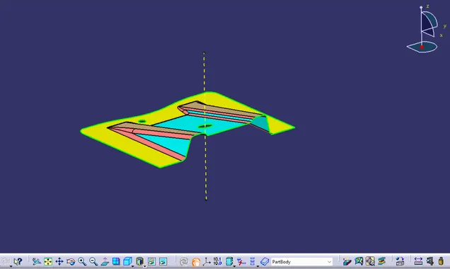
GIVEN CLASS A SURFACE:
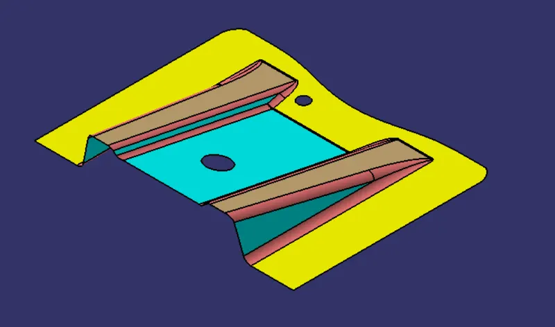
Connectivity of the class A surface is done using join and boundary command.
PROCEDURE FOLLOWED:
- TOOLING AXIS CREATION
- DRAFT ANALYSIS CLASS A SURFACE AND FINAL COMPONENT
- CREATION OF CLASS B SURFACE
- CREATION OF CLASS C SURFACE
- CREATE SOLID BODY FROM SURFACE USING "CLOSE SURFACE"FEATURE.
1.TOOLING AXIS CREATION
Tooling axis is the direction in which mold or core and cavity opens. The ejection of the part from mold depends on the draft. A zero draft can result in difficult or no ejection due to shrinkage. It is recommended to add a minimum of 0.5 to 1 degree upto 3 degree of the draft for non-textured surface & 3 to 5 degree of draft for textured surfaces.
To create tooling axis using bisecting method the following steps are folllowed,
Check visually which is the best possible tooling axis amoung the 3 axes.
Along x it is possible but expensive and y is not possible.z is the best possible tooling axis.
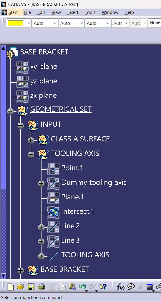
- point is created at the centre of the hole,
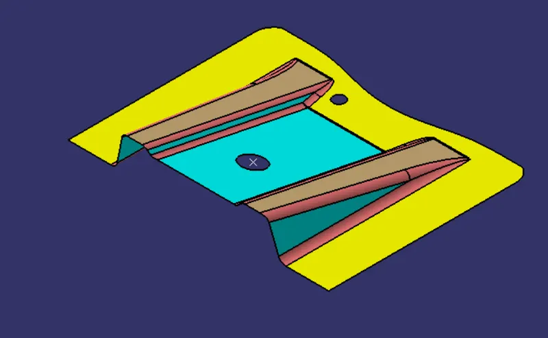
- YZ plane is created at the point and intersect the class a surface with the plane,
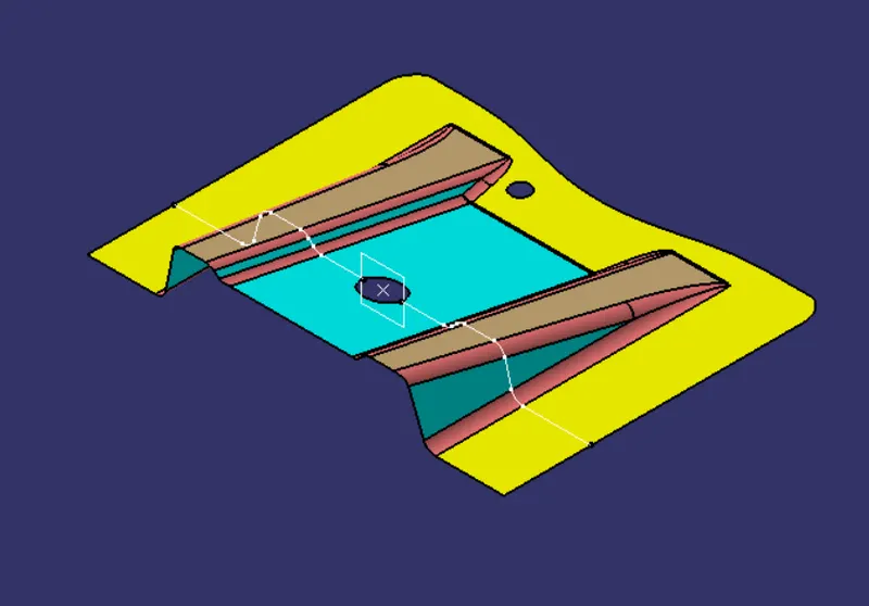
- After creating the intersectin curve ,two lines are created using the intersecting curve .Then bisecting line is created using those 2 lines.
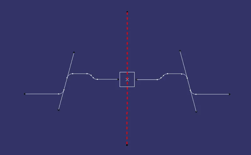
- This way the tooling axis is created.
2.DRAFT ANALYSIS:
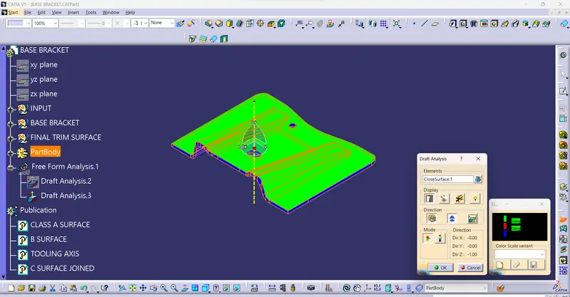
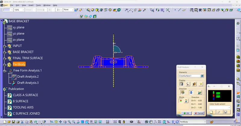
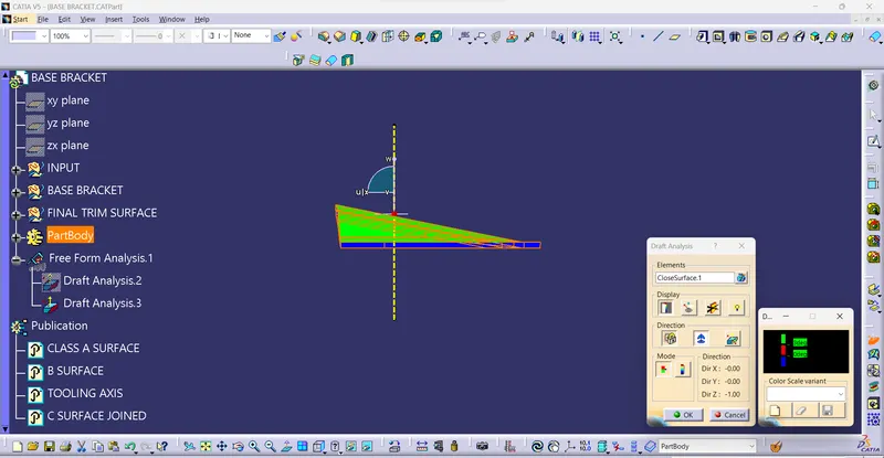
The draft angle is the amount of taper perpendicular to the parting line for molded or cast parts. It is measurable in degrees. Because plastic shrinks and sticks on molding surfaces as it cools, we draft the walls of the plastic part so that it ejects or breaks free from the molding surfaces more easily and without dragging. To reduce the risk of damage to the elements and ensure ejection, a functional injection molding part must have drafts on both the cavity and core sides
- 3 Degrees is a nominal draft angle
- 7 Degrees is considered for Textured surface parts
ADVANTAGES OF DRAFT:
- Reduces the possibility of part damage due to friction during the release
- Ensures a uniform, smooth, unscratched finish
- Reduces overall cooling time by reducing or eliminating the need for unusual ejection setups
- Reduces mold wear and tear
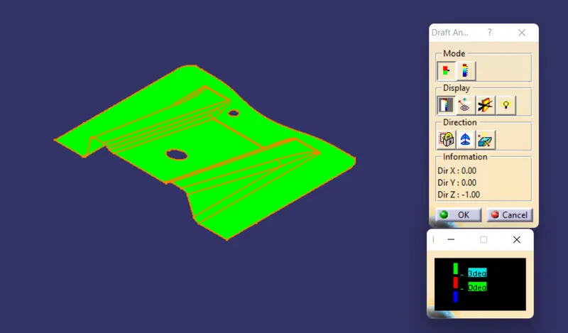
STEPS FOLLOWED IN DRAFT ANALYSIS:
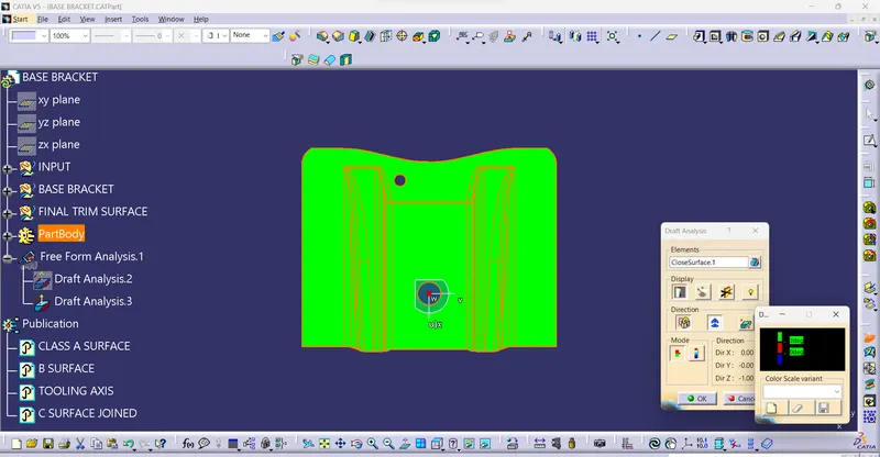
- First change the created part into material.
- Click on the compas and plase in the tooling direction.
- Use the lock command to fix the compass
- Click on the surface and apply the draft angle(minimum draft angle is 3 degree)
3.CREATION OF CLASS B SURFACE
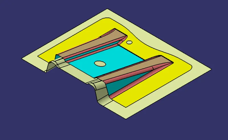
Class B-Surface is extracted from the A-surface and it is offseted at 2.5mm in downward direction
4.CREATION OF CLASS C SURFACE
C-Surface connects the class A-Surface and B-Surface. It is created using Sweep command. Boundry of the class A-Surface is swept along the tooling direction.
5.CREATION OF SOLID BODY:
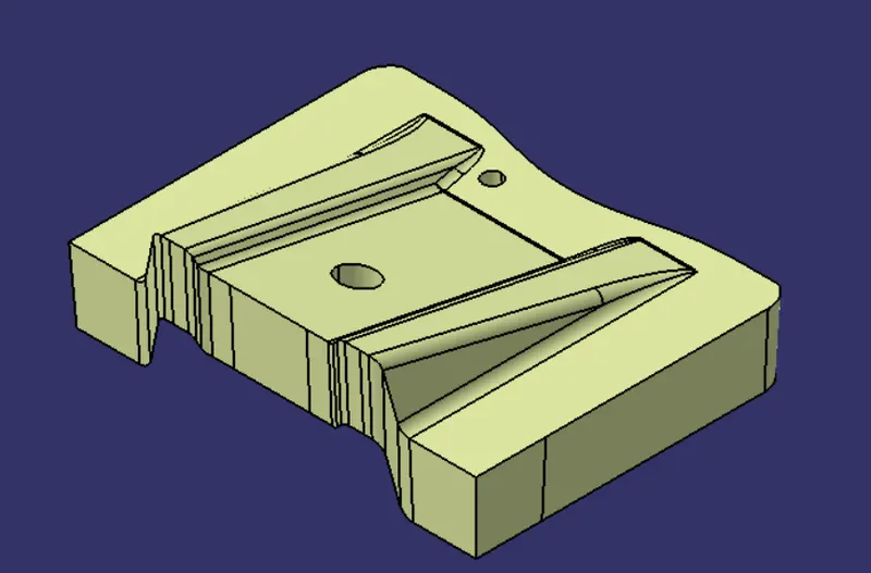
The solid body is creted from the colsed surface shown below,
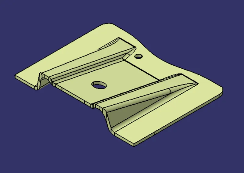
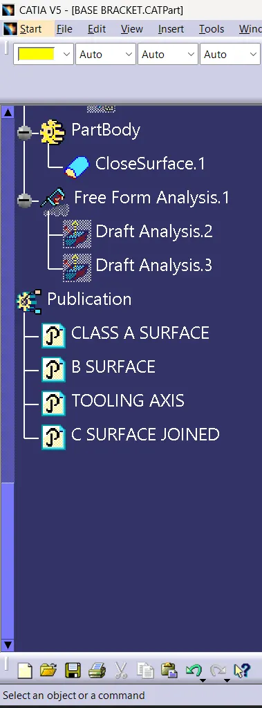
The solid body is created using the close surface feature.
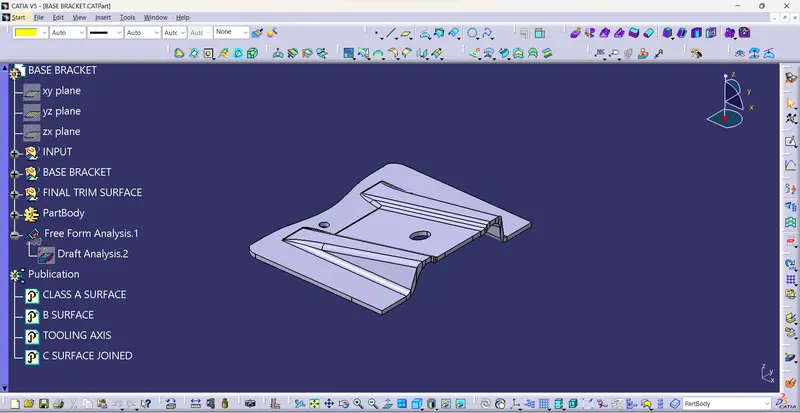
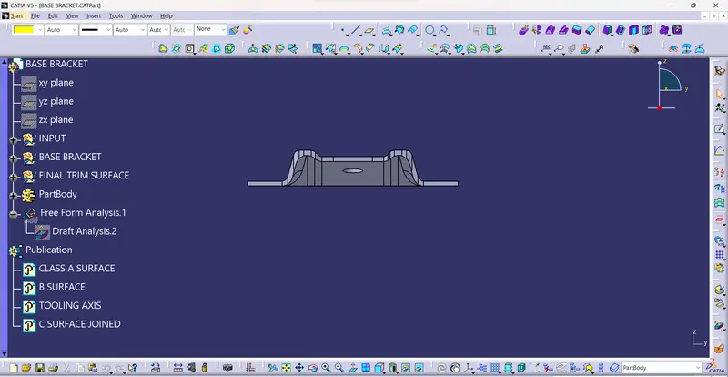
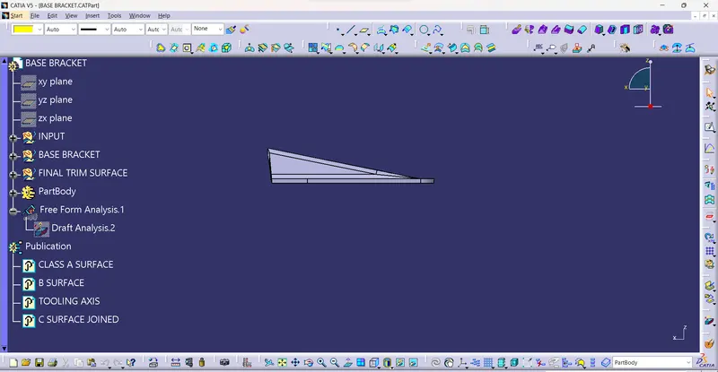
Draft analysis
GEOMETRICAL TREE STRUCTURE
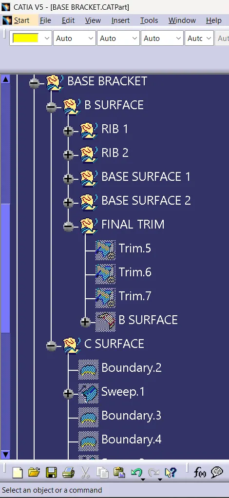
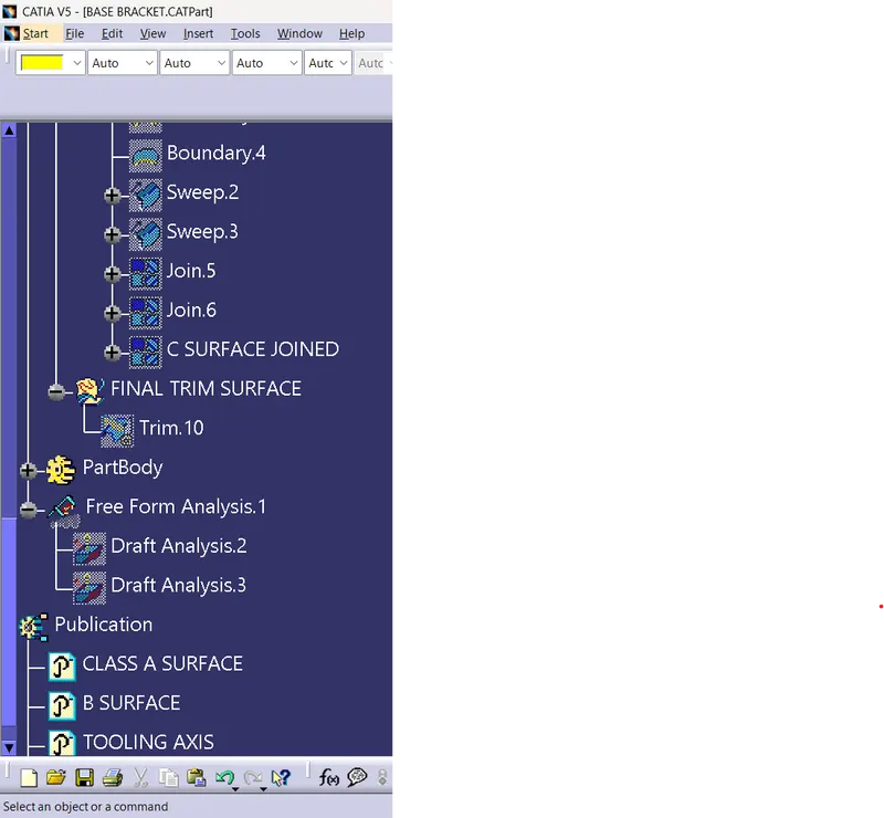
PART TREE STRUCTURE
CONCLUTION:
Base basket plastic component is created using given class A surface.