Week 9 - Challenge 1 - Base Bracket Design
Aim:-
To create the Base Bracket plastic component from the given Class-A surface. Also to create the tooling axis by meeting the requirements of the draft angle and perform the Draft analysis on the model.
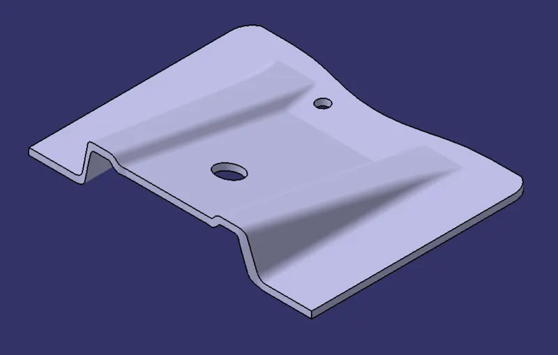
Fig.1: Isometric View of the Model.
Tooling Axis:-
The direction with respect to the component in which the mould opens and closes is the tooling axis. In other words, the mould is built from two separate halves (Core and Cavity) and the tooling direction basically defines the direction in which the mould pulls apart.
Procedure to create the tooling axis:-
For this model, Bisecting Method was used to create its Tooling Axis:
- First, the given Class-A surface was observed carefully from every direction and found that a dummy tooling Axis can be created along the z-axis.
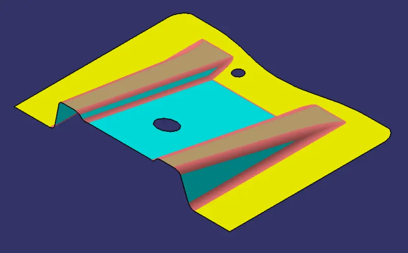
Fig.2: Given Class-A surface. - Then, a point was created at the centre of the hole.
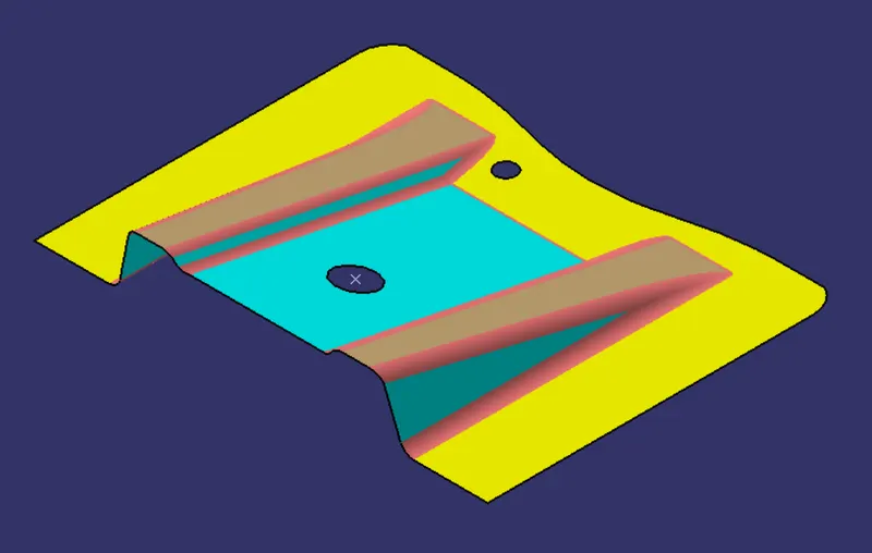
Fig.3: Point at the centre of the hole. - After that, a line was created along the z-axis and which was passing through that point and named as dummy tooling axis.
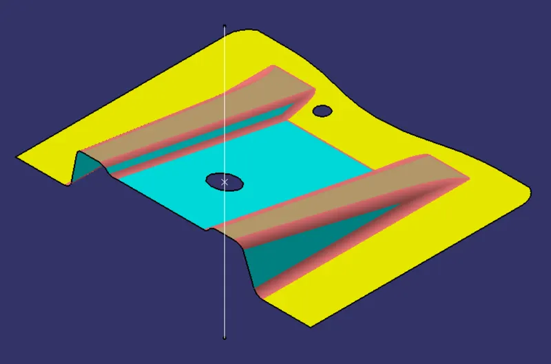
Fig.4: Dummy Tooling Axis. - Then, a plane was created at the centre of the hole which was parallel to the yz-plane.
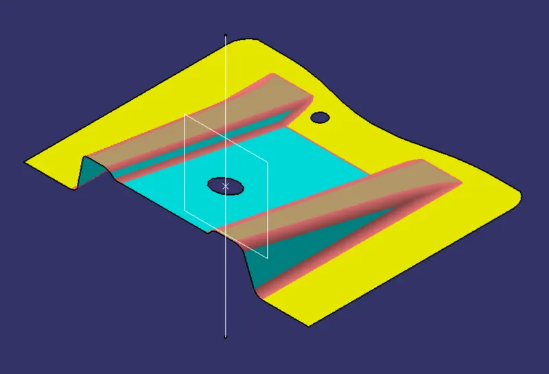
Fig.5: Plane created at the centre of the hole. - Then, the intersection of the surface was taken along that created plane.
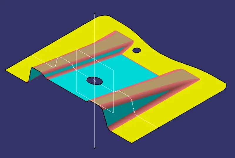
Fig.6: Intersection of the surface along the plane. - Then, the intersection curve was observed carefully and two lines were created along the lines of the intersection curve which seems almost parallel to the dummy tooling axis.
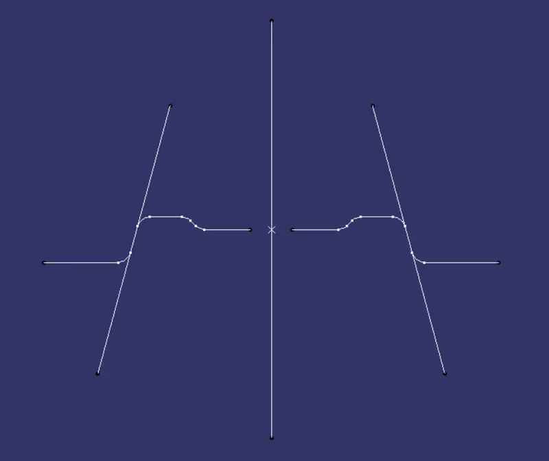
Fig.7: Two lines on the intersection curve. - At last, the bisecting line was created using these two lines and named as Tooling Axis.
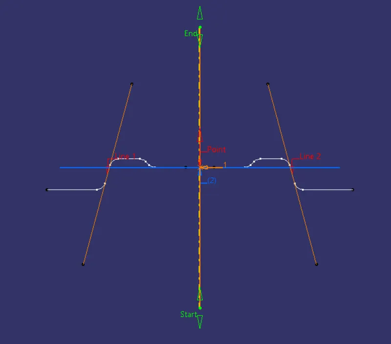
Fig.8: Bisecting line. - Hence, the Tooling Axis was created.
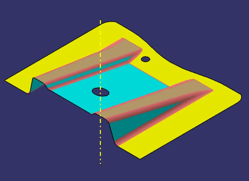
Fig.9: Tooling Axis.
Draft Analysis:-
The draft analysis is used to analyze whether our part model created in CAD is manufacturable based on the draft angle and the tooling direction provided. It also enables us to detect if the part will be easily removed from the mould or not. The ejection of the part from the mould depends on the draft. A zero draft can result in difficult or no ejection due to shrinkage. It is recommended to add a minimum of 0.5 to 3 degrees of the draft.
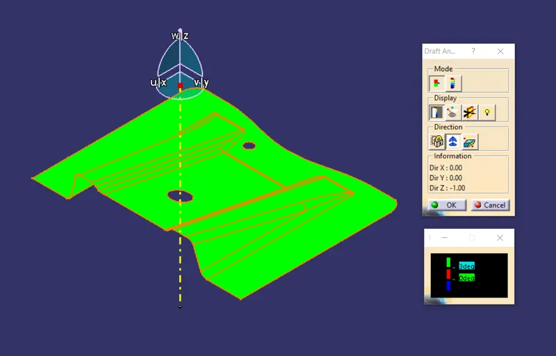
Fig.10: Draft analysis of the given Class-A Surface.
Model:-
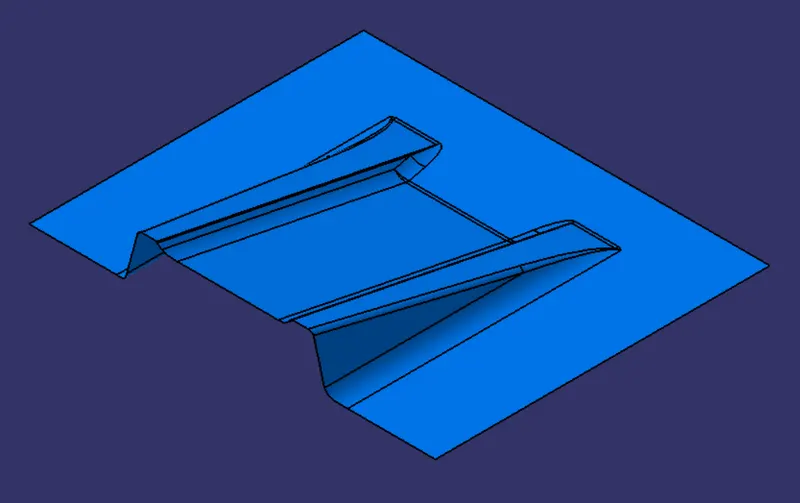
Fig.11: Class-B Surface.
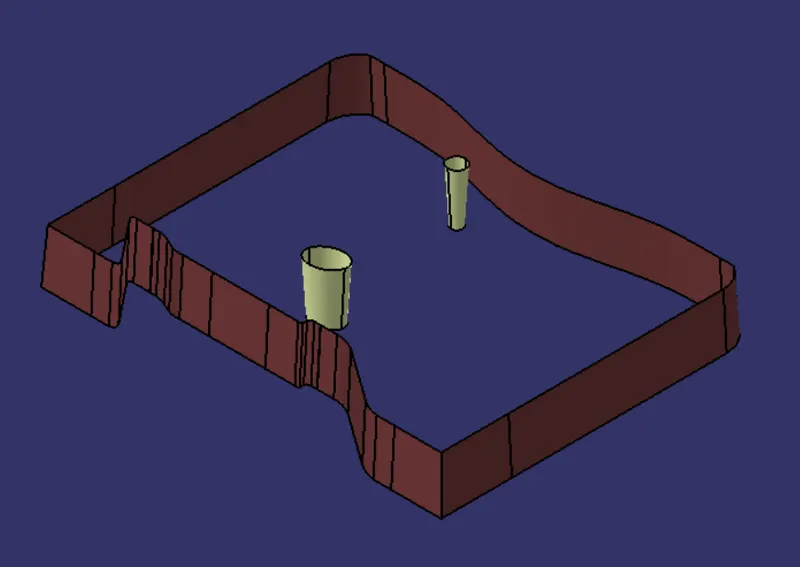
Fig.12: Class-C Surface.
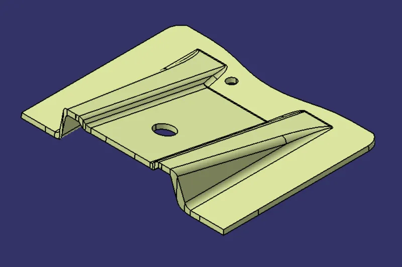
Fig.13: Joined Class-A, Class-B, and Class-C Surface.
Fig.14: Solid Model.
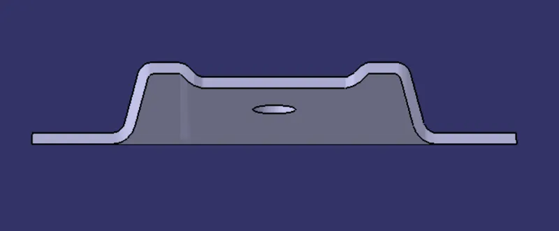
Fig.15: Front View of the Model.
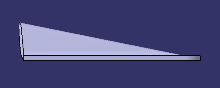
Fig.16: Side View of the Model.
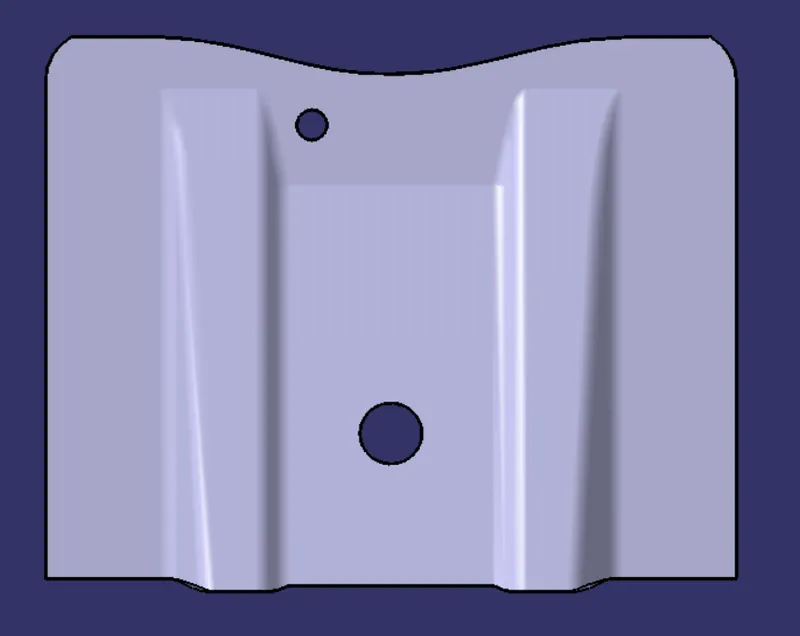
Fig.17: Top View of the Model.
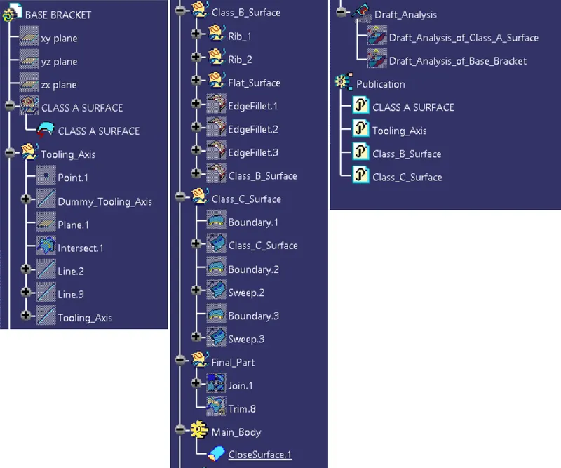
Fig.18: Tree Structure for the Geometrical Sets and the Part Body of the Model.
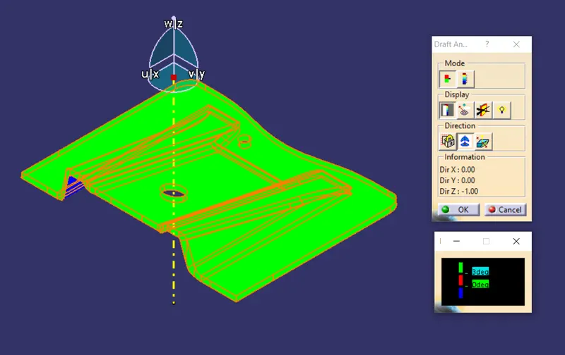
Fig.19: Draft analysis of the Solid Model.
Conclusion:-
The Base Bracket plastic component was created from the given Class-A surface. Also, the Tooling axis was created and perform the Draft analysis was performed.