Week 9 - Challenge 1 - Base Bracket Design
AIM
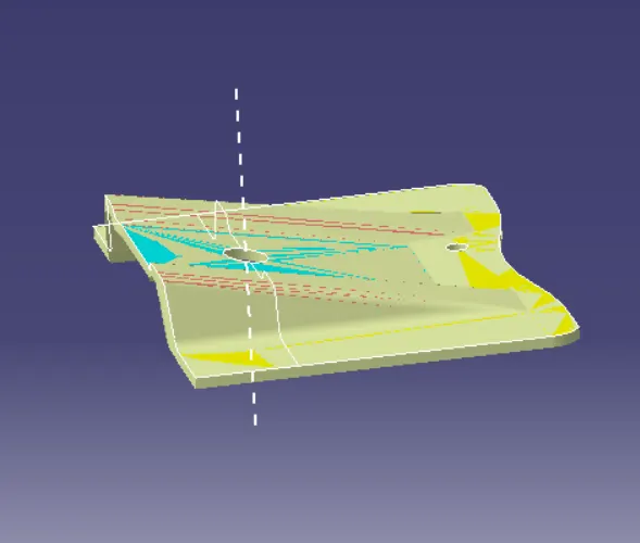
Create the Base Bracket Plastic component through the given Class-A surface. To begin with, the tooling axis for the given Class-A Surface should be created meeting the requirements of the draft angle and at the end perform the Draft analysis on the model.
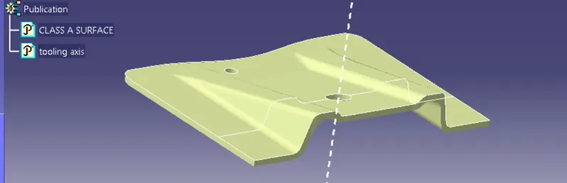
GIVEN CLASS A SURFACE
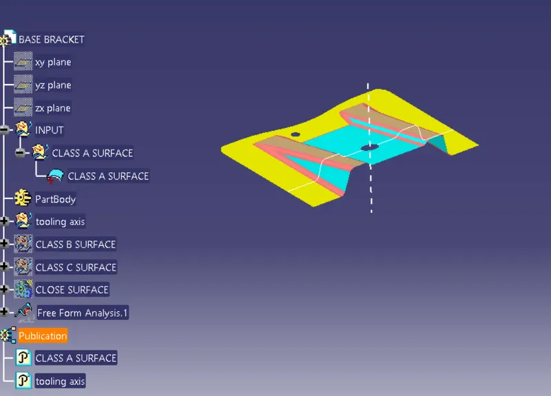
TOOLING AXIS CREATED IN CLASS A SURFACE
Tooling axis
In this direction in which the mold opens and closes selected the appropriate tooling direction and created a dummy tooling axis then created main tooling axis by using the bisecting method.
BISECTING METHOD
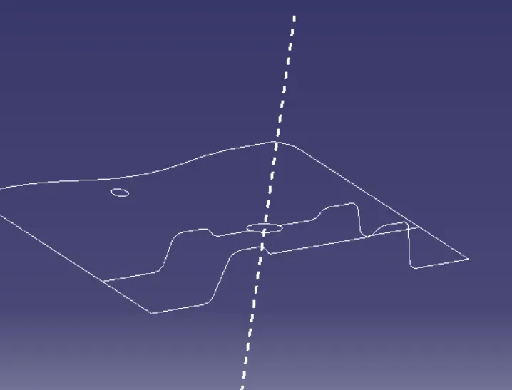
This method is used for creating the main tooling axis .creating the intersection of the given class A surface along y plane.Select the surfaces in the tooling direction and drawn the lines along this surfaces .If this lines are parallel bisecting line shows the error in order to know given surface is toolable or not. Then create a bisecting line using this two inclined line ,this bisecting line is the main tooling axis.
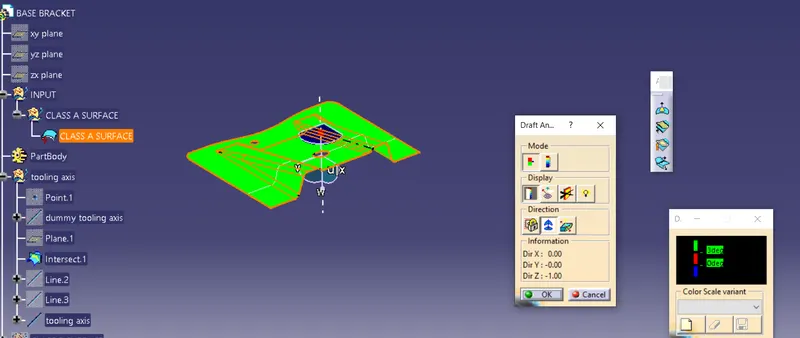
DRAFT ANALYSIS ON CLASS A SURFACE
Draft is a taper applied to the faces of the part that prevent them from being parallel to the motion of the mold opening. This keeps the part from being damaged due to the scraping as the part is ejected out of the mold
draft analysis is performed on the given class A surface using the main tooling axis to check the surface has minimum draft (3 degree).The given surface has minimum draft angle .
CLASS B SURFACE
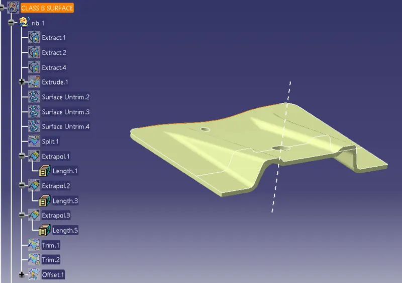
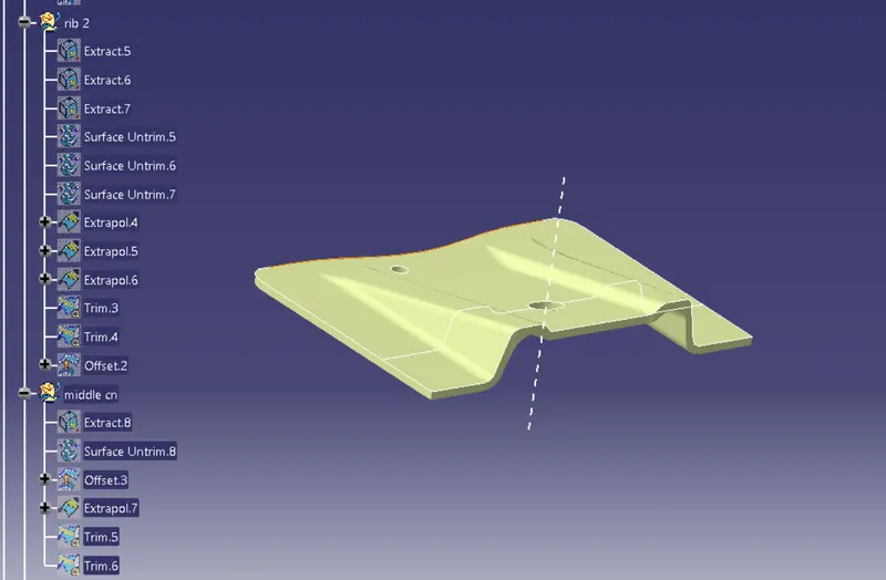
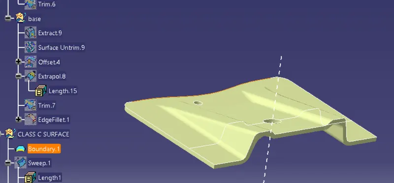
Class B is an engineering surface it created from the input class A surface . Extracting the required surface then untrim,extrapolate and offset the surface in the required thickness .finally trim the surfaces and create the class B surface
CLASS C SURFACE
The class C surface created by using boundary lines of class A surface and sweep it with reference to the main tooling axis.Use sweep with draft direction then provide accurate draft angle and length .draft direction should be main tooing axis.class C surface
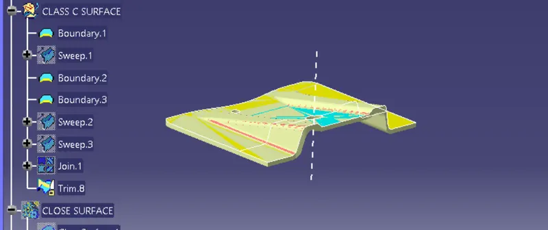
- Then join class A surface with class C surface and finally trim the joined surface with B surface to get the final closed surface body
DRAFT ANALYSIS OF SOLID PART
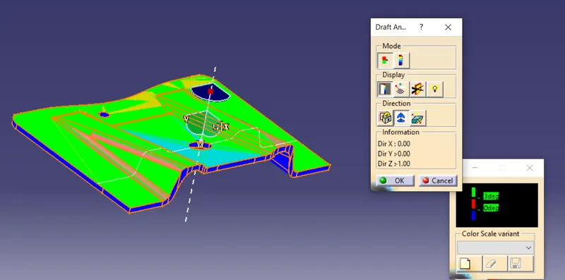
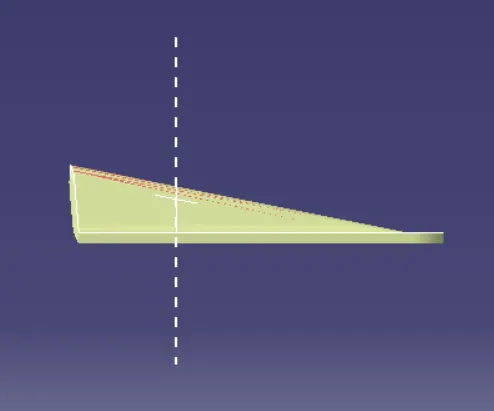
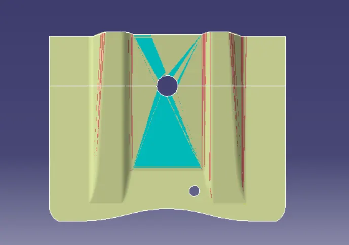
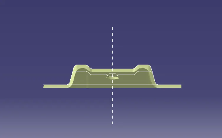
TREE STRUCTURE WITH DIFFERENT VIEWS
PUBLICATION