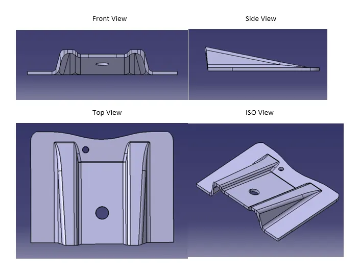
Week 9 - Challenge 1 - Base Bracket Design
Create the Base Bracket Plastic component through the given Class-A surface. To begin with, the tooling axis for
the given Class-A Surface should be created meeting the requirements of the draft angle and at the end perform
the Draft analysis on the model.
Thickness of Plastic Part - 2.5 mm
Input : Base Bracket .CATPART
Base Bracket .STEP
Base Bracket .IGES
use .STEP file for designing.
This file contains the Class - A Surface of the component.
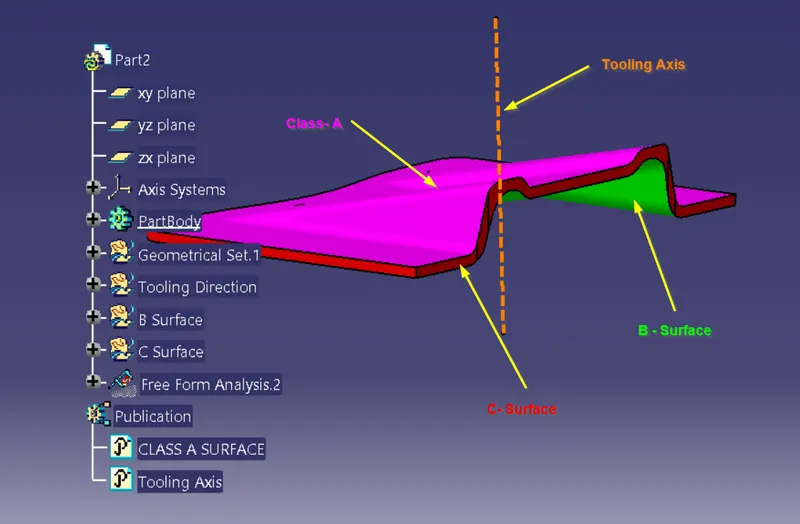
The class A surface has different colored surfaces for easy understanding.
Tooling Direction :
In order to manufacture the desired shaped component, the Tooling direction and Draft angle must define while designing.
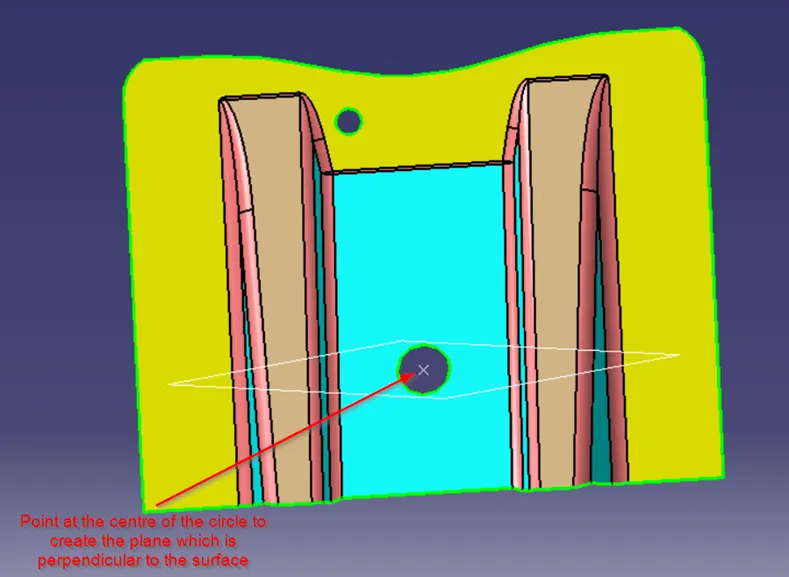
Here we have created a perpendicular plane to the component.
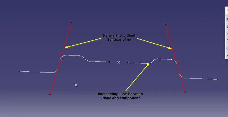
By using the Intersection command, got the intersection curve.
Draw an extended line on a slant surface with the reference of the intersection curve.
Then, create one bisecting line between two slant surface lines, which will be the
Tooling Axis for the component.
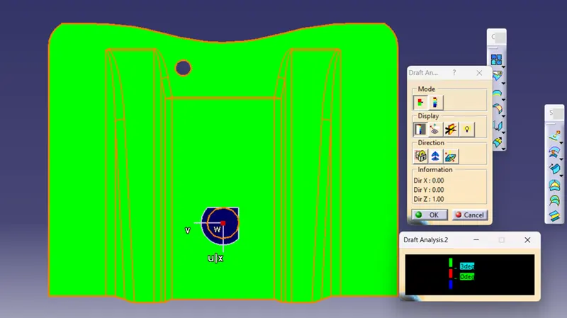
Draft analysis of class A:
Geometrical Set:
Close Body Component: