Week 9 - Challenge 1 - Base Bracket Design
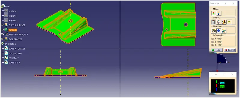
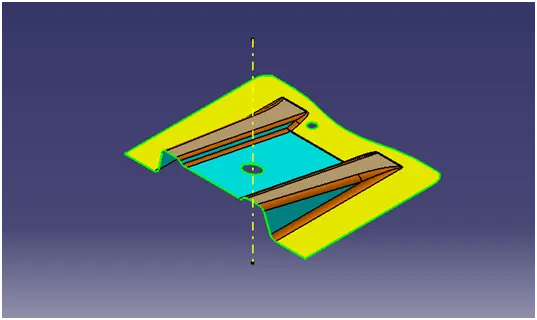
challange: Create the Base Bracket Plastic component through the given Class-A surface. To begin with, the tooling axis for the given Class-A Surface should be created meeting the requirements of the draft angle and at the end perform the Draft analysis on the model.
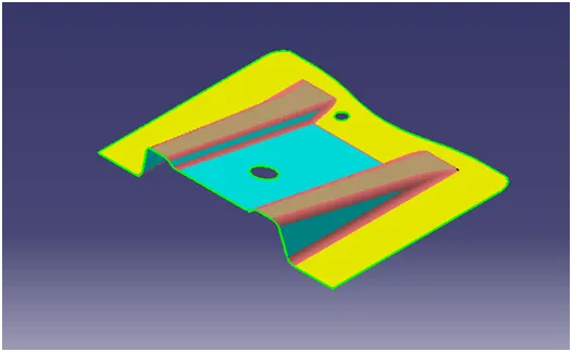
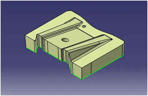
GIVEN CLASS A SURFACE
Class A in the surface created by the stylist and it is the outer most part visible
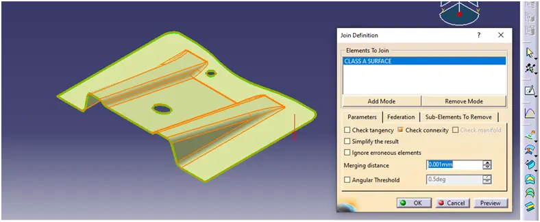
Check the continuity of the component by using the join command.
TOOLING AXIS
Check for best axis for tooling axis, initially create a dummy tooling axis at the hole center,
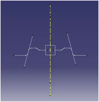
For main tooling axis create a plane at hole at YZ plane using hole center as ref point, take a intersect at that plane & interaction line will be formed, using the line command create a line at side lines and extend the lines and create the bisecting line and it will be main tooling axis.
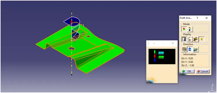
Draft analysis of the Class A surface
Draft analysis is the the process of analyzing the component to check the angle provided to the surface min draft required for a component is 3o.
Class B surface
It the surface created using the thickness of the component.
First extract the planer surface form the class A surface.
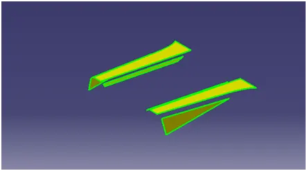
Un trim the surfaces.
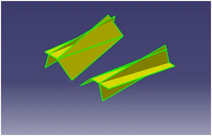
Extrapolate them.
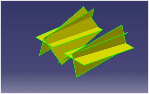
Trim the extended surfaces
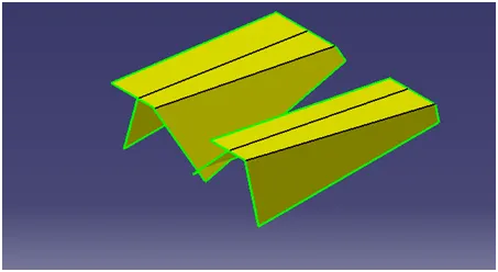
Offset the surfaces (Ribs) at 2.5 mm thickness
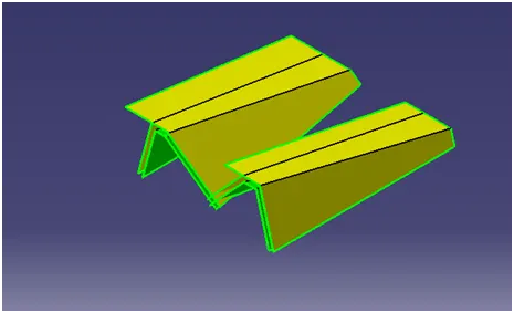
Extract the base surface, untrim the surface, extrapolate them & offset 2.5mm
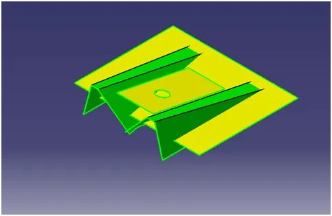
Trim the unwanted surface
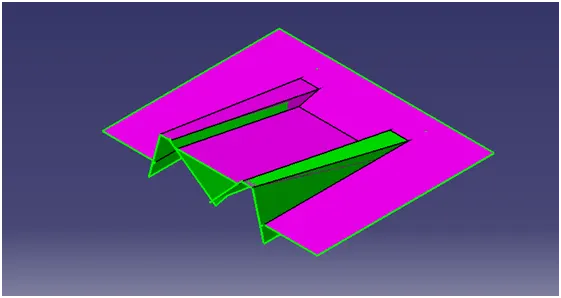
Provide fillet to edges 5.5(3+2.5) radius +thickness
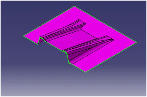
Class C surface
It is the surface joining the A & B surfaces
Create a boundary of the class A surface
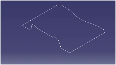
Create a sweep using the boundary & holes
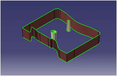
Join the class C surface with class A
Trim the unwanted extended surfaces.
Draft analysis of final part