Week 9 - Challenge 1 - Base Bracket Design
AIM :
Create the Base Bracket Plastic component through the given Class-A surface. To begin with, the tooling axis for the given Class-A Surface should be created meeting the requirements of the draft angle and at the end perform the Draft analysis on the model.
Thickness of Plastic Part - 2.5 mm
TYPES OF SURFACES :
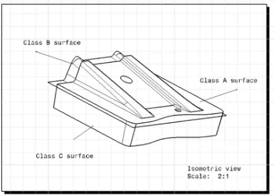
There are three types of surfaces which we used in surfaces deisgn. They are Class A, Class B, Class C.
Class A is the surface that is created by the concept sketches made by free hand sketchers. The finalised sketch is then fed to the computer and a 2D surface is created out of it by the use of a software like Alias. This computerized design is known as Class A surface.
Class B is a reference surface that is created by the design engineer and is a copy of the class A surface that is at a distance equal to the thickness of the part.
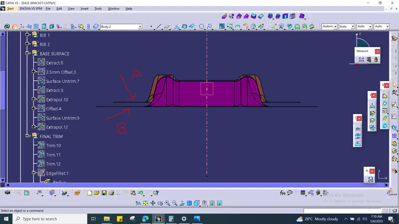
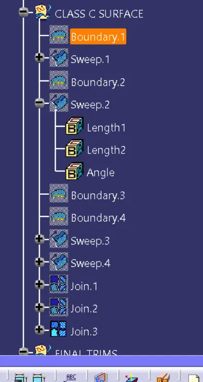
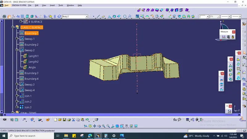
Class C is again a reference surface that is created by the design engineer to connect Class A and Class B surface also known as the side wall of the surface.
EXPLANATION OF TOOLING AXIS CREATION :
Initialy styling team given the class A, with the help of class A surface we dervied the final finished the surface. Before that we need to create a YZ plane and tolling axis for pre draft analysis.
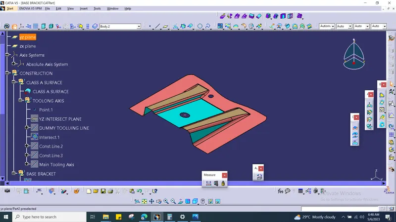
First we need to give the proper gementry name in tree structure. Then create the point in existing circle with that create a YZ plane. This will helps to create a Bisecting line which we see details in below.
With thepoint we need to create a Dummy tooling axis for better understanding purpose.
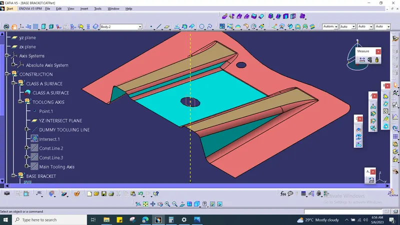
Then with the help of Dummy tooling line and YZ plane we need to create the Bisecting line and with two more construction line. We will get the Tooling line. Then Highligting into Yellow for better understand and unhide all remaing line and planes.
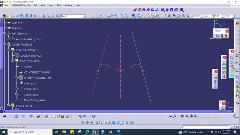
SURFACE B :
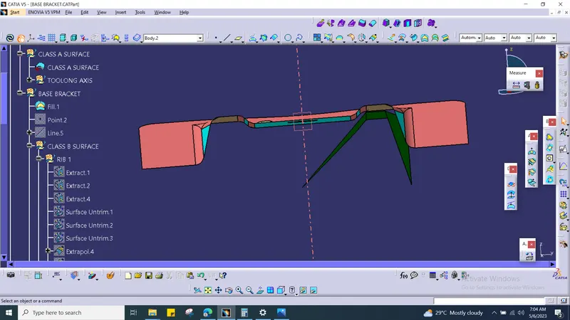
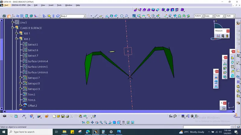
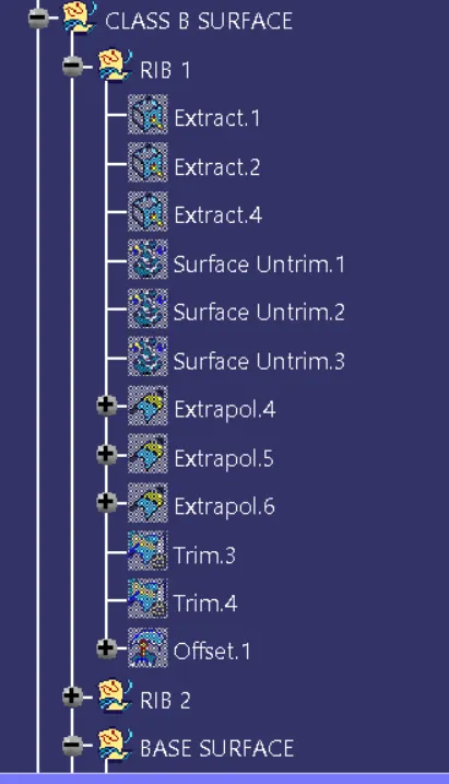
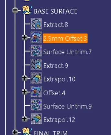
After finishing tolling axis, we need to prepare the Rib 1 and Rib 2 with the help of surface B. Offset into 2.5mm. Exact the B surface into 2.5 mm and do untrim and then extrapool follwed by trims. we will get the like this bellow image as well.
Rib 2 surface :
BASE SURFACE :
C SURFACE :
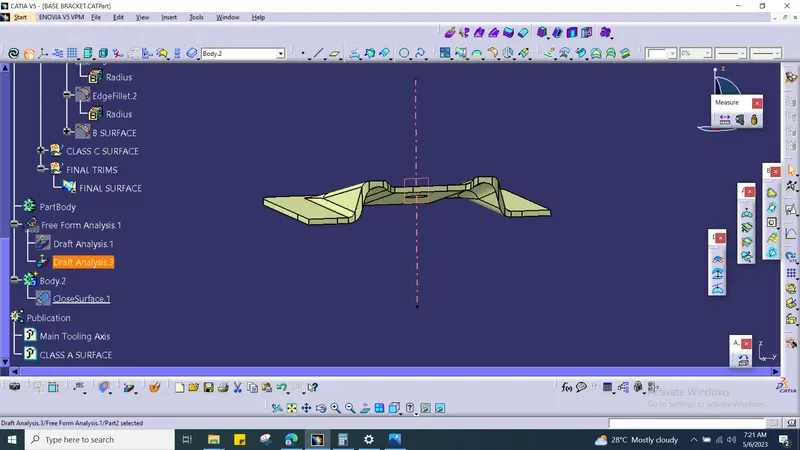
FINAL TRIM:
ZERO BOUNDARY CONDITION :
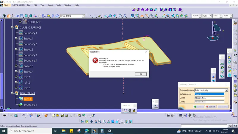
PRE DRAFTING ANALYSIS :
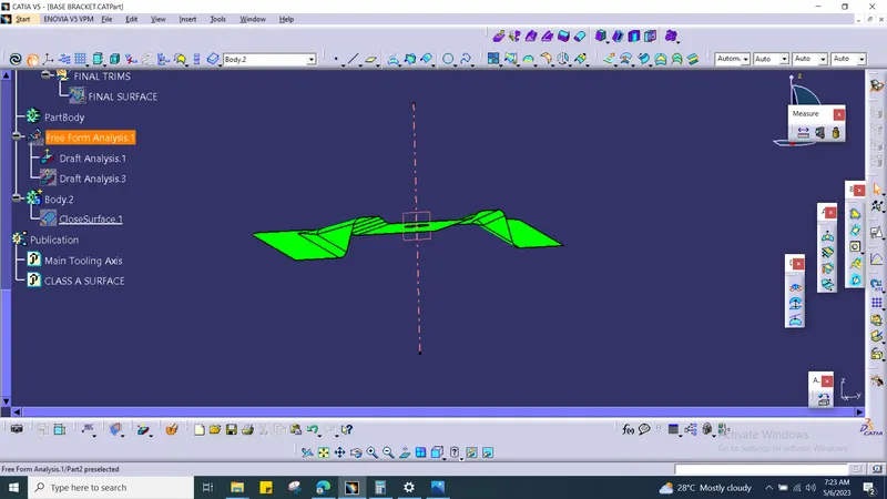
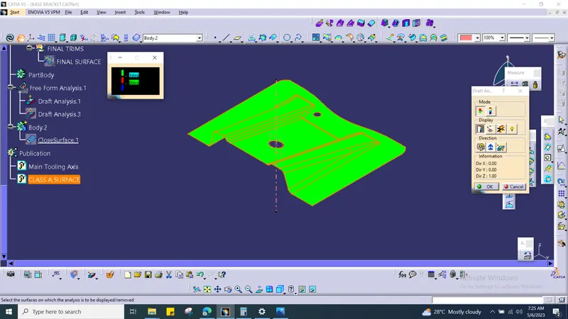
Once you started the draft analysis next we need to placed the compass in to the class A surface. And then click into A surface. We will get the image like this with the draft angle of 2.9 degree toward outside direction.
FINAL SURFACE DRAFT ANALYSIS :
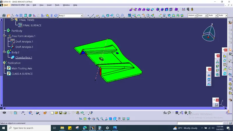
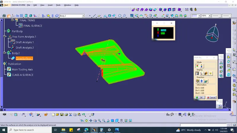
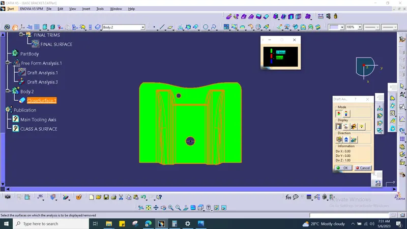
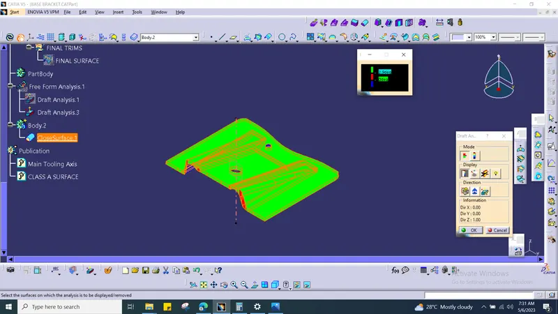
Again we need to fianl surface draft analysis. All step are similary. we need to placed the compass in to the tooling axis toward upside direction. And then click into C surface. We will get the image like this with the draft angle of 2.9 degree toward outside direction.
PROBLEM FACED :
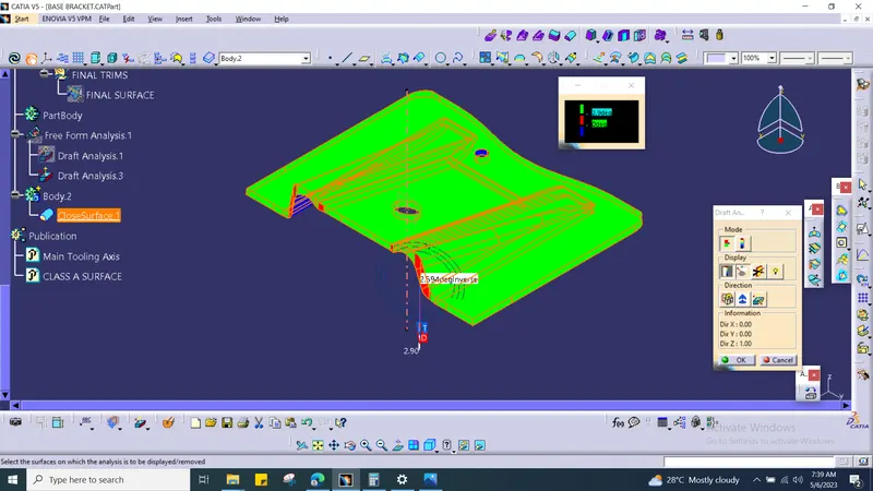
If you see above image we are getting some area in red color. This is not best practice. So I measured that surface Iam getting into 2.594 degree draft angle so which is acceptable.
FRONT VIEW:
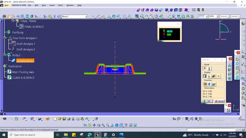
SIDE VIEW :
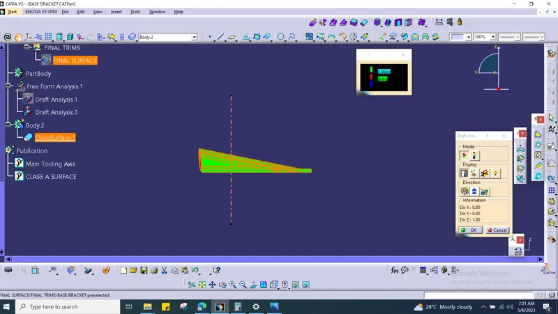
TOP VIEW :
ISOMETRIC VIEW:
CONCLUSION :
As per above instruction given we created the class B and C surface with proper gementry constain, Tooling axis and Bisecting line. And we made draft analysis of both pre surface and final surface, we are getting positive results.