Week 9 - Challenge 1 - Base Bracket Design
Aim
To Create the Base Bracket Plastic component through the given Class-A surface. To begin with, the tooling axis for the given Class-A Surface should be created meeting the requirements of the draft angle and at the end perform the Draft analysis on the model.
Requirement
Thickness of Plastic Part - 2.5 mm
Reports to include
- Explaining the draft analysis and the tooling axis creation
- An explanation should be given on the way of creating the tooling axis.
Draft analysis
The draft angle is the angle between the normal to the surface and the direction of the pull of the tooling during the molding process, The draft analysis tool to evaluate the draft angle of a product and adjust it accordingly.for the ease of manufacturing process. its is one to three degree allowed as maximum, or else the manufuring will be hard.
Tooling axis
the tooling axis is axis that defines the direction of the mould and cast to be joined for the preparation of the die.
the bisecting method is said to be the choosing the line of direction in by bisecting .
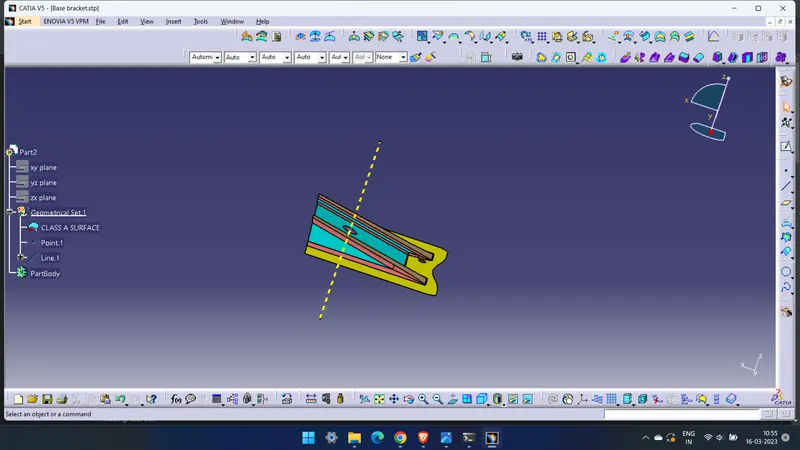
the given Class A surface
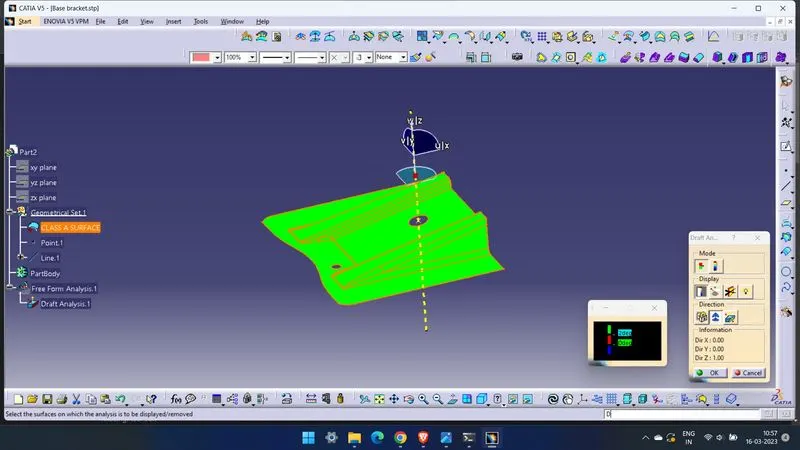
draft analysis on the given surface with the tooling axis made.
then the Class B surfaces are made by extract tool and offseting and joining them and also an expole is done around the surface for 10mm
then the class C is made from the boundary and sweep tools, the before triming state looks like this.
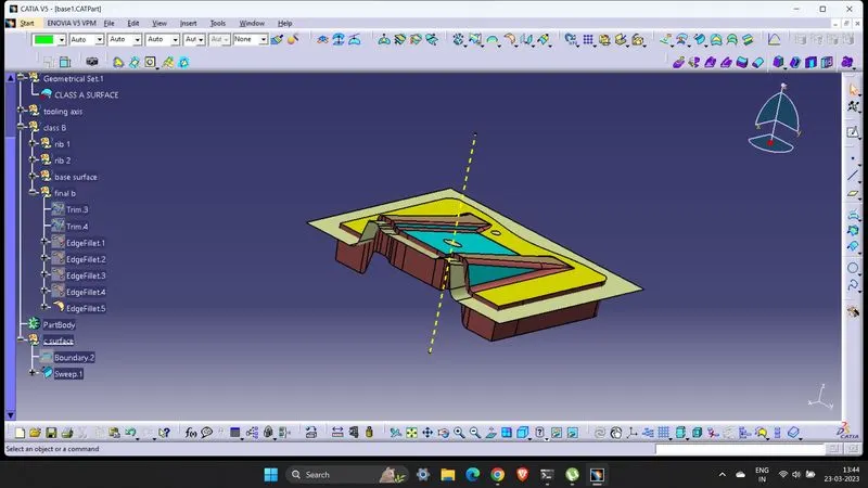
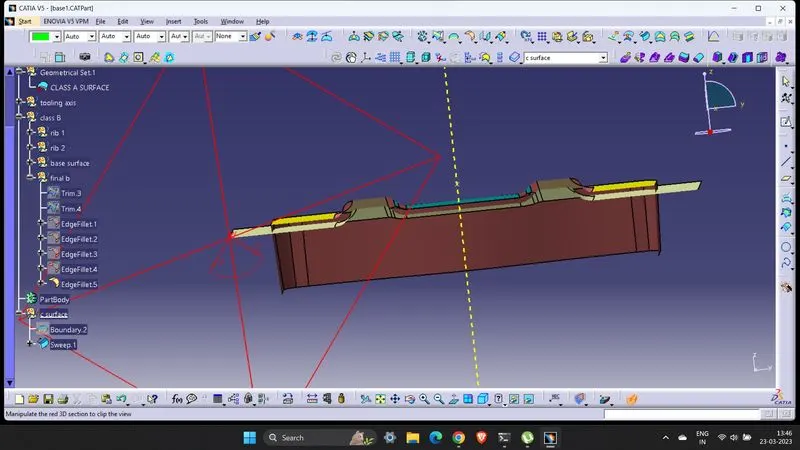
the joinings are confimed by dynamic section tool.
then trimings are done
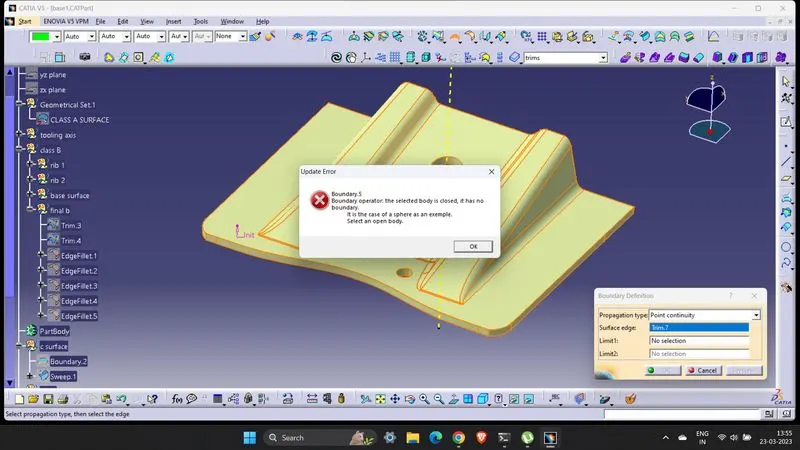
No , gap fond while testing with boundary tool.
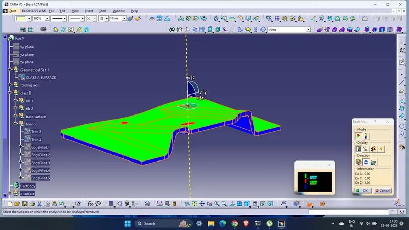
The Final result
Created the Base Bracket Plastic component through the given Class-A surface. the tooling axis for the given Class-A Surface is created meeting the requirements of the draft angle and the Draft analysis on the model. is done with Thickness of Plastic Part - 2.5 mm