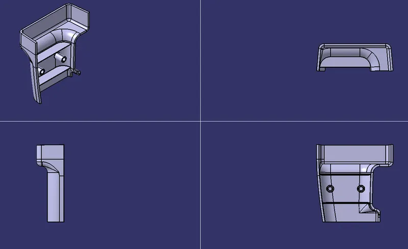
Week 9 - Attachment Feature Creation (Ribs & Screw Boss) - Challenge 1
REPORT:
AIM: to create the class B and class C surface and then we have to create the ribs and screw boss for the component using design rules and calculations.
PROCEDURE: first we will recieve a class A surface as an input and we have to create class B and class C surface for it before creating the class B surface we have to create the tooling axis for creating tooling axis we have to check the tooling direction for this component we have tooling direction in y direction to create the tooling axis first we will extract one of the surface of the component after extracting the component we have to create a point and then we have to create a line using that point by point direction method and we name that line as a TOOLING AXIS.
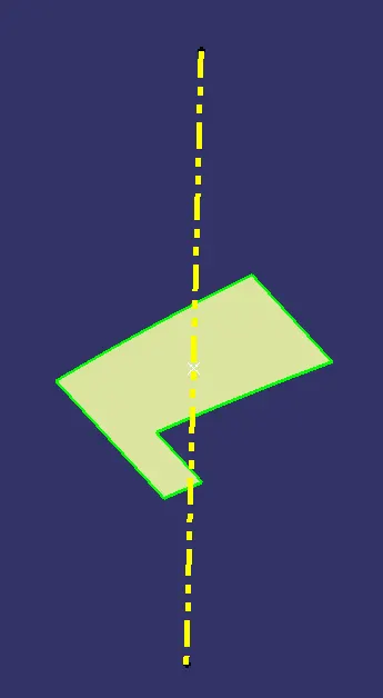
after creating the tooling axis we have to create the class B surface to create class B surface for this type of component we cannot extract each part and then do the further operation instead of doing that we can offset that entire component to required direction after doing the offset we have to hide the class A and we have to take deep look in the class B that there is any gap or not if we found a gap we have to work on that gap by using multi extract or multi section solid after working on that gap we will receive the output as follows:
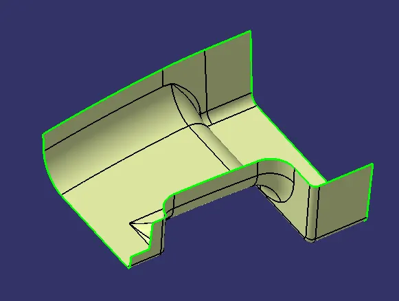
after receiving the output as above image we have to create the class C surface for class A to create class C we have to create a boundary on the A surface and then we have to use the sweep command with draft direction and with surface reference and we will receive the output as follows:
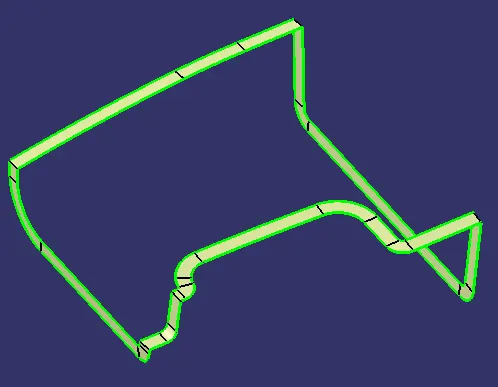
after receiving the C surface we have to join the class A and class C Surface using the join command and we will receive the output as follows:
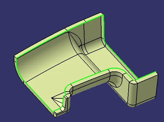
after receiving the class A and class C as a single component we have to trim itb with the class B surface to get an proper output and after getting the final trim we have to make it as asolid part because the component which we received is hallow inside so making it as a solid part we have to go back to part design and we have to use close surface command to close the component after making it as the solid body we have to hide the final trim and our output will be as follows:
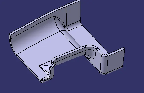
after getting the solid part we have to create the B side features that is nothing but nothing but ribs and screw boss first we will create the ribs by using designing rules and its calculations.
to create the ribs we have to draw a sketch on the required position by creating a plane on that position and then we have to extrude the sketch to be required height.
HOW TO FIND OUT THE HEIGHT OF THE RIBS?
to find out the height of the ribs we have some calculations for it i,e,.the rib height has to be multiply by *5 of the thickness of the component for instance our component is 2.5mm thickness then the height of the rib should be 2.5*5=12.5 after getting the proper height of the rib we have to find the thickness of the rib.
HOW TO FIND THE THICKNESS OF THE RIB?
to findout the thickness of the rib we have some calculations for it i,e,. the thickness of the rib has to be multiply by 0.4* of the thickness of the component for the instance our component is 2.5mm thickness the the thickness of the rib should be 2.5*0.4=1.
after getting the proper thickness and height for the rib has to drafted for a minimum of 0.5mm and it has to be filleted for 0.25mm and we will receive the output as follows:
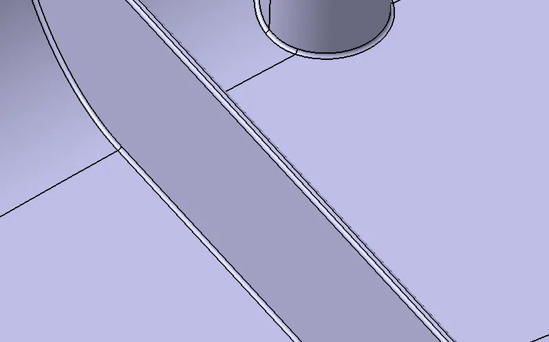
after getting the first rib we have to create the second rib to the required distance using the same design rules and calculations and we have to add both the ribs to the main part body using boolean command and we have to make it has a single part body. after creating the both the ribs we have to create screw boss for the part body.
CREATION OF SCREW BOSS.
to create the screw boss first we have to know the sizes of the screws for instance if we are created M4 screw we have to create the whole dimension of the screw and then we have to create the outter diameter(screw boss) with the engineering calculations i,e. is 40% of the wall thickness that is nothing but 1.5mm each side after getting the thickness of the outter diameter (screw boss) we have to pad it up to the required height.
HEIGHT OF SCREW BOSS.
There are some calculations for calculating the height of the screw boss the calculations are as follows
the height of the screw boss should be 3 times the outter diameter of the screw boss for example our component is 2.5mm thickness and the outter diameter of the screw boss is 4 then the height of the screw boss should be 3*4=12.
after getting the height of the screw boss we have to do draft for the screw bosses for a minimum of 0.5mm and the screw boss should have a minimum fillet value of 0.25mm after giving the fillet value the screw bosses has to be added to the main part body. after doing all this we will receive the output as follows:
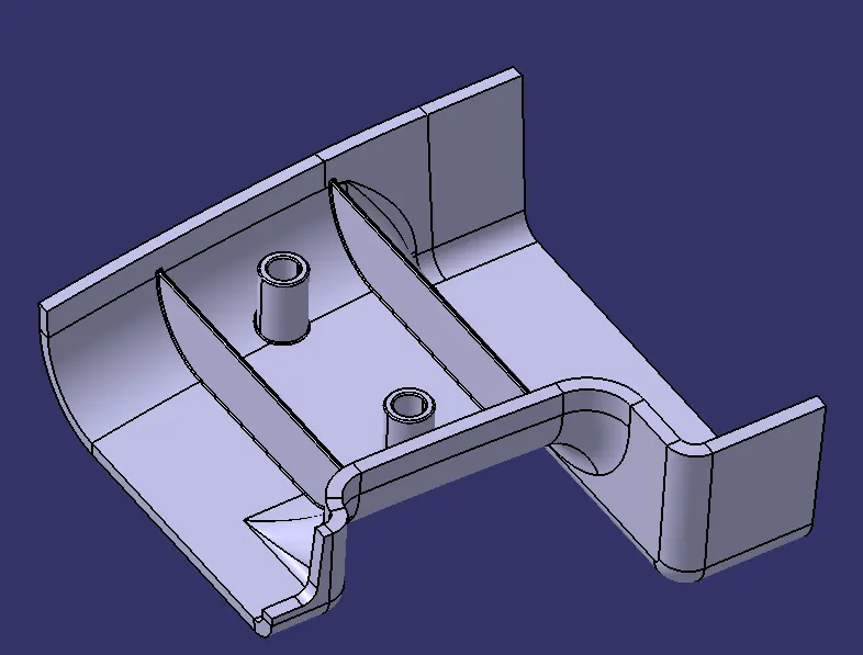
after receiving the output we have to check for rib root thickness by taking intersection and then drawing a tritangential circle on it by intersecting the three dots that is fillets and the base the rib root thickness image will be as follows:
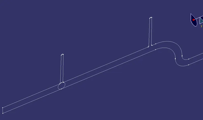
after getting the proper output we have to do the draft analysis for solid component
DRAFTING ANALYSIS METHOD.
Insert> analysis> feature draft analysis.
using draft command and selecting the compass tool in the direction tool bar and draging it to the tooling axis and then locking it their and using their compass and checking the drafting angles
the drafting angle should be maximum 3 degree and it should not increse more than that after placing the compass we get a red dot on the curser. By clicking the red dot on the component rthe colour of the component will change the top becomes green and the bottom becomes red colour.
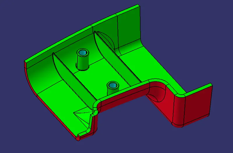
but here we will get a issue that the C surface is not following the A surface that is because the sweep which we done is 90 degree with refrence surface so it will drafted on core itself.
we will get the output in two colours one is green colour on top and red colour on the bottom which means the green colour is 3 degree and the red colour is projecting that the draft is less than 0 degree and the red colour was not the original colour before but for our refrence we have changed it to red colour so that we can find it easily that it has an negative value.
after finishing the checking of drafting analysis and then our component is ready for manufacture.
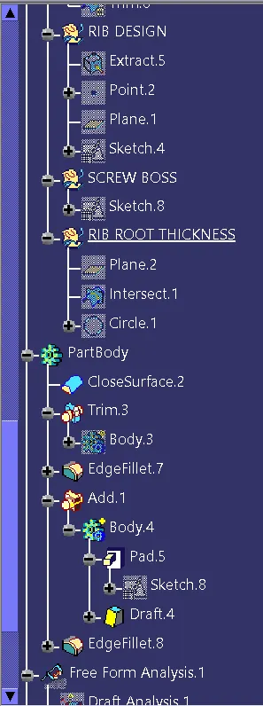
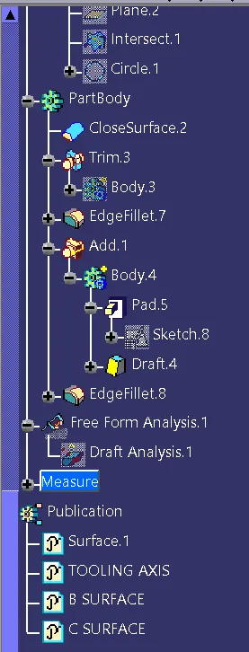
TREE STRUCTURE:
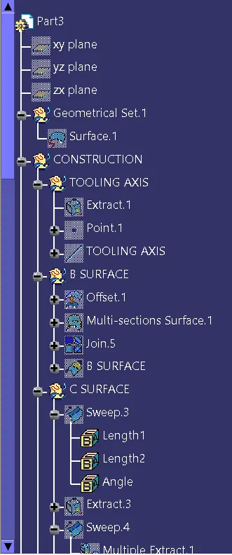
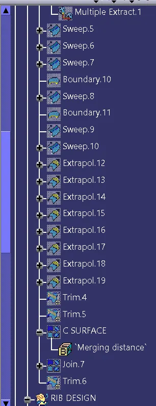
DIFFERENT VIEWS: