Week 9 - Attachment Feature Creation (Ribs & Screw Boss) - Challenge 1
OBJECTIVE
To Create the rib for the Drill Handle considering the design rules
TOOLING AXIS
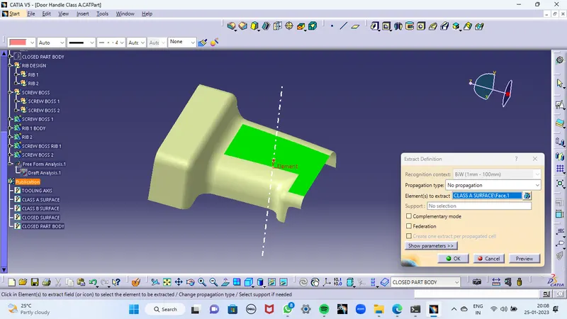
FOR CREATING A TOOLING AXIS WE NEED TO EXTRACT A SURFACE FROM A CLASS-A SURFACE AND MAKE A POINT AT THE CENTRE AND MAKE A LINE WITH REFERENCE TO THAT POINT IN THE Y-DIRECTION. NOW THIS WILL BE OUR TOOLING AXIS.
CREATING B SURFACE
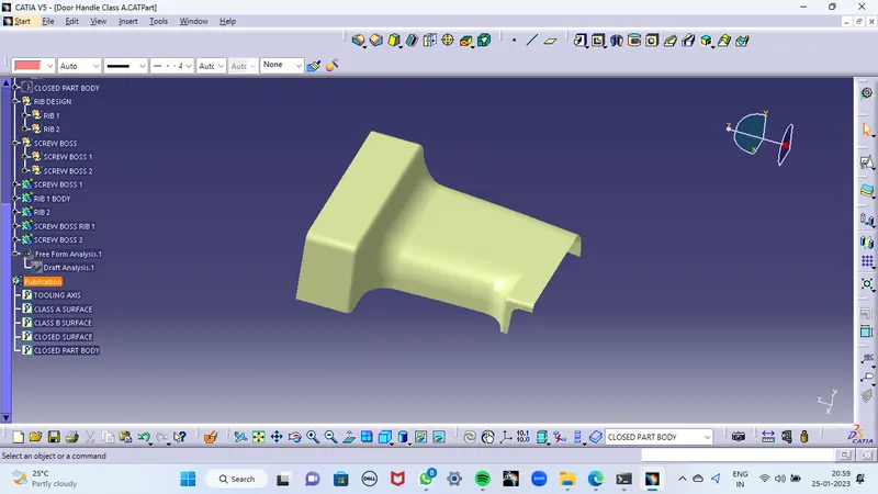
FOR CREATING B SURFACE WE NEED TO OFFSET OUR CLASS-A SURFACE FOR 3mm. NOW WE CAN FIND A PATCH ON IT. SO FIRSTLY WE NEED TO SOLVE THIS. THEN WE GET A SURFACE LIKE BELOW. THIS WILL BE OUR CLASS-B SURFACE
CREATING C-SURFACE
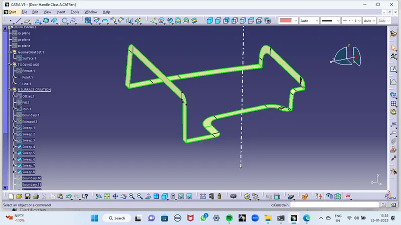
FOR CREATING C- SURFACE WE NEED TO SWEEP THE BOUNDARY OF THE CLASS-A SURFACE. THEN WE GET A SURFACE LIKE BELOW. THIS WILL BE OUR CLASS-C SURFACE
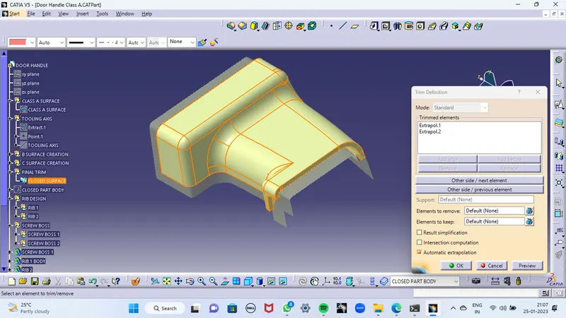
JOIN CLASS-C SURFACE TO THE CLASS-A SURFACE. AND UNHIDE THE EXTRAPOLATED B-SURFACE AND TRIM THEM TOGETHER TO GET A COMPLETELY CLOSED SURFACE LIKE BELOW. THIS WILL BE OUR FINAL SURFACE
AFTER GETTING THIS MAKE IT A PART BODY
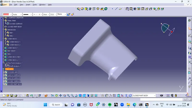
DRAFT ANALYSIS
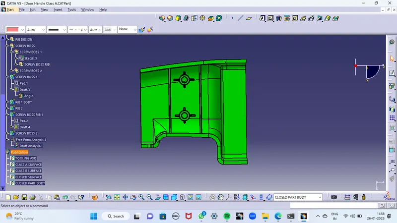
AFTER GETTING THIS PART MODEL WE NEED TO DESIGN A B-SIDE FEATURES
B-SIDE FEATURES
RIB CREATION
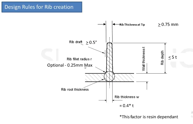
Ribs are usually designed to Improve the Strength of the Plastic parts without increasing the thickness of the component.
For creating a rib, firstly we need to extract a surface from the B-surface and make a point on the surface then create a plane parallel to this point. In this plain itself, we create a sketch for the rib. After that, we extrude the sketch according to the design rules.
here, the thickness of the wall is t= 3mm
so that the height of the rib is H= 5*t
, therefore, height if the rib H = 5*3=15mm
Width of the rib W= 0.4*t
W=0.4*3=1.2mm
Fillet value = 0.25mm
Draft angle = 0.5deg
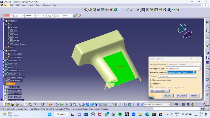
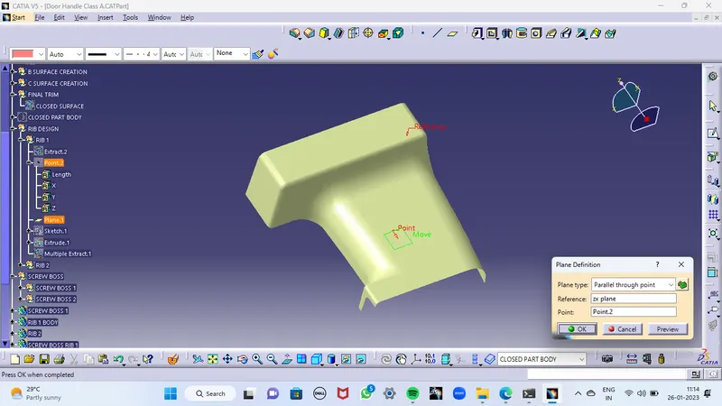
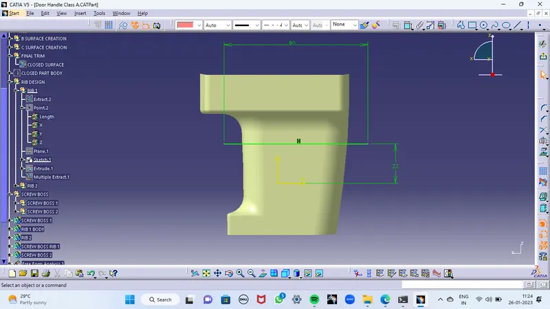
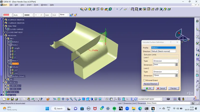
The same procedure we have to repeat for rib 2
SCREW BOSS DESIGN
It helps to screw components together. Screws are secondary features that are on B-surface. Bosses are used to attaching & assembly features of many components
General Guidelines for Bosses:
- Draft - 0.5 degrees on the walls of boss
- Thickness - Typically 40%* of the nominal wall at the base.
- Height to Diameter Ratio - 3:1
- Radii - 0.25mm maximum radii.
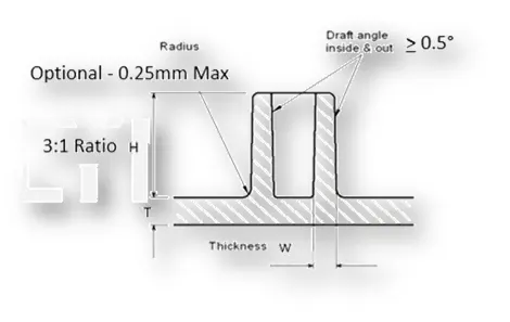
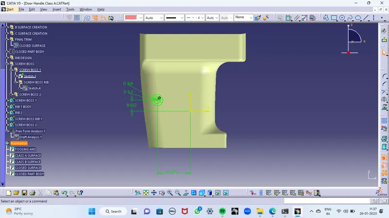
WITH THE REFERENCE TO THE PARALLEL PLAIN WE CREATE A SKETCH FOR THE SCREW BOSS ACCORDING TO THE SCREW BOSS DESIGN RULES
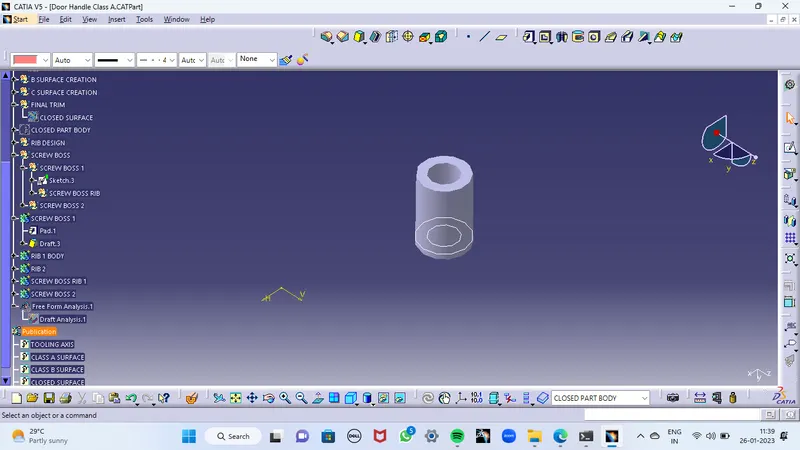
MAKE SURE TO DRAFT THE PAD WHICH IS HAPPENED. HERE THE DRAFT ANGLE IS 0.5mm
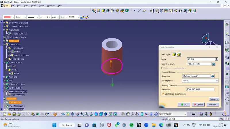
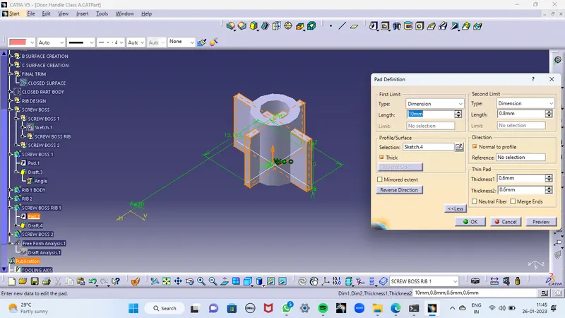
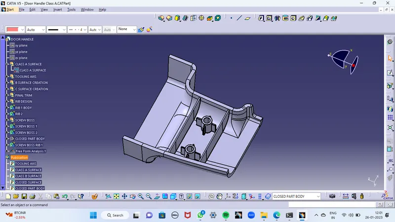
Likely do the same operation for screwboss rib also. Perform union trim and add with the maim component then our design will look like below
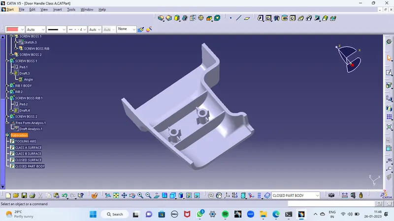
TREE STRUCTURE
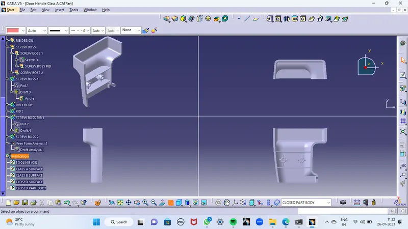
DIFFERENT VIEWS
CONCLUSION:
- The Tooling axis and the SolidCAT part with B Side Features are created from the given Class A Surface and Draft Analysis is Performed.
*****THANK YOU*****