Week 9 - Attachment Feature Creation (Ribs & Screw Boss) - Challenge 1
OBJECTIVE:
Create the rib for the Drill Handle considering the design rules mentioned
Create the Screw boss for the Drill Handle considering the design rules mentioned
CLASS A:
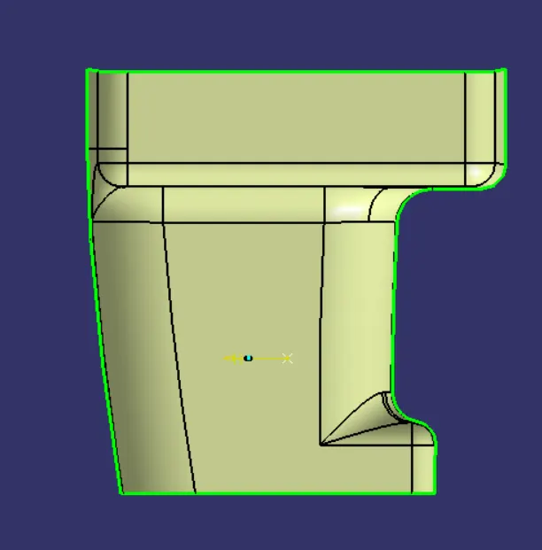
GENERATING TOOLING AXIS:
1.First the connectivity of the class A surface is checked by using boundardy option on the surface.
2. Extracting the base surface and creating a point on the surface and creating a axis system.
3. The intersion option is used along XY plane and the drawing direction is assumed to be along the interstion of the curves.
and creating two lines along the surface and using bisecting line option tooling direction along XY plane is created.
4. By bisecting the zy tooling axis and zx axis direction . Main tooling axis created.
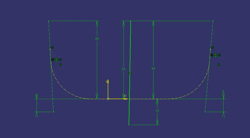
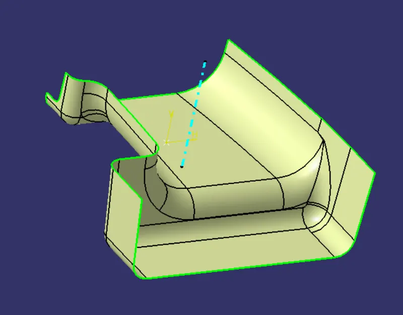
DRAFT ANALYSIS OF CLASS A
CLASS B:
1. CLASS A is offseted for 2.5mm
2. open patch is closed by extracting the boundary and using Multi-Section surface command.
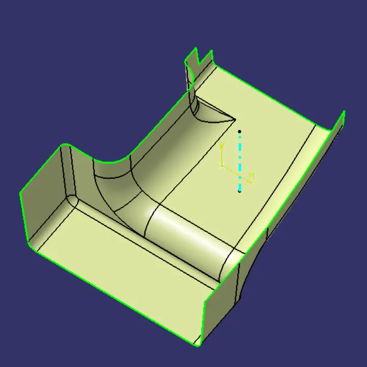
CLASS C
1. The boundary surfaces are created by extracting the boundary and sweeping individually with reference to surface.
2. Fillanlly all the boundary surfaces are trimmed by extrapolating the edges for crossing.
3. class C is created.
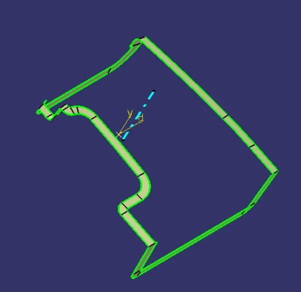
FINAL TRIM:
1. The Class A and Class C are joined together and trimmed with Class B.
2. The final trim is checked for open regions using boundary option.
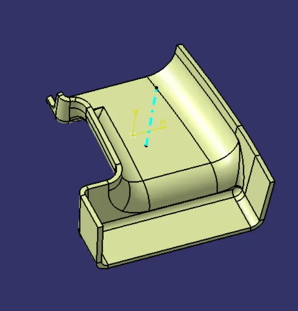
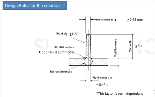
DESIGN RULES TO BE FOLLOWED FOR RIB CREATION:
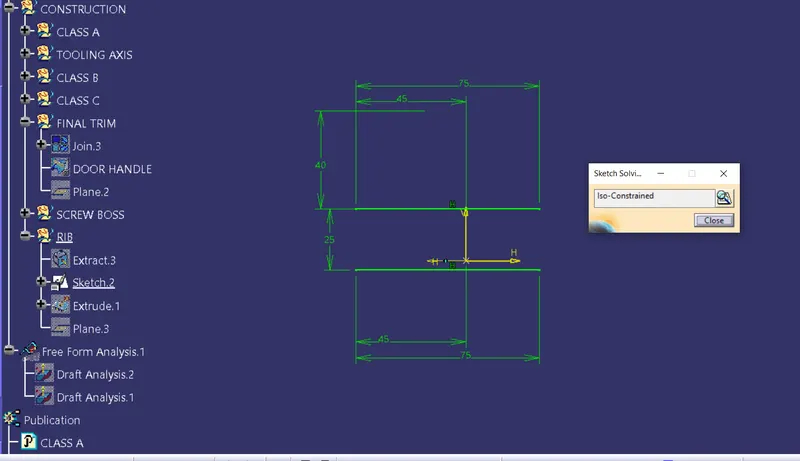
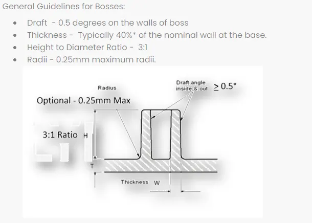
DESIGN RULES TO BE FOLLOWED FOR SCREW BOSS CREATION
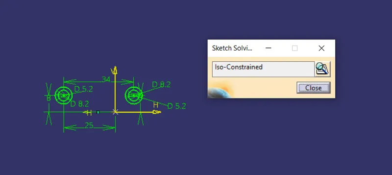
FINAL COMPONENT:
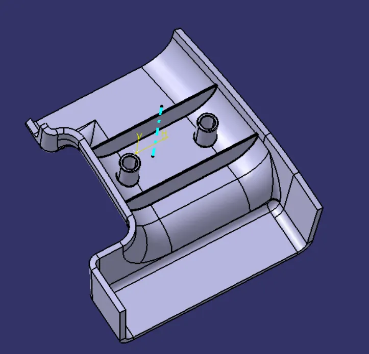
ISOMETRIC:
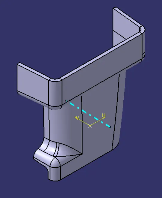
FRONT:
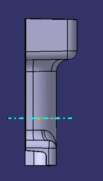
LEFT:
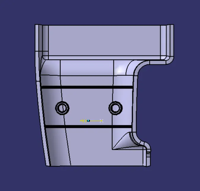
TOP:
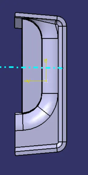
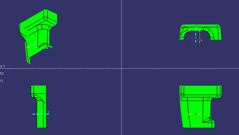
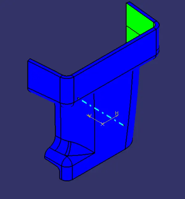
DRAFT ANALYSIS OF FINAL COMPONENT:
ISOMETRIC:
FRONT:
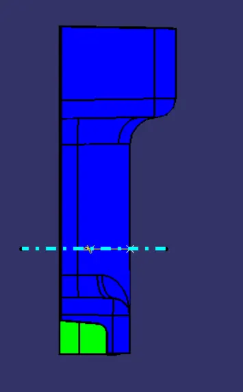
LEFT:
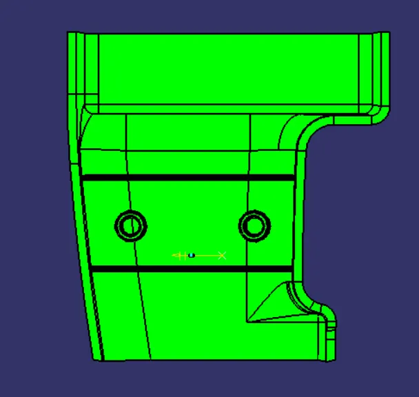
TOP:
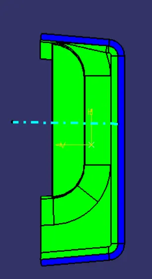
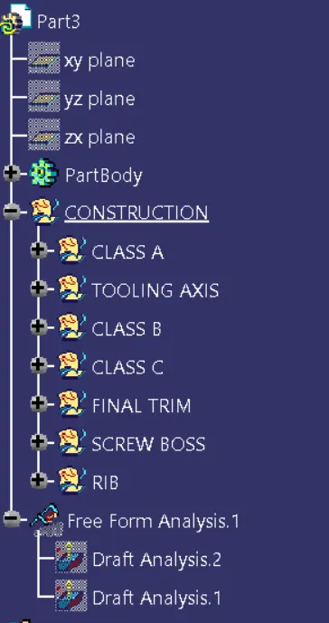
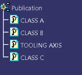
TREE STRUCTURE: