Week 9 - Attachment Feature Creation (Ribs & Screw Boss) - Challenge 1
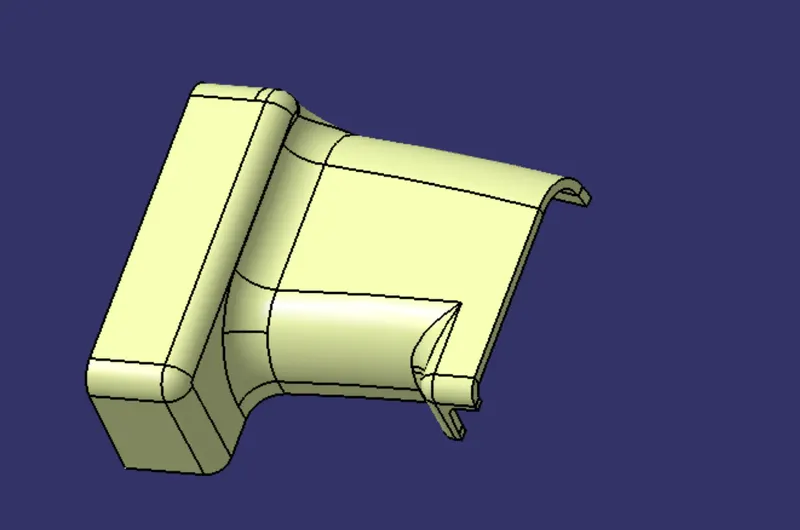
DOOR HANDLE
TREE structure :
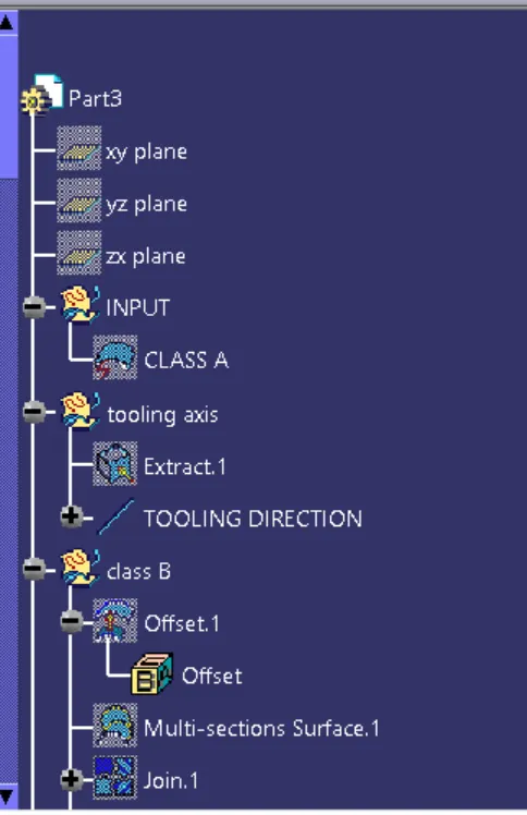
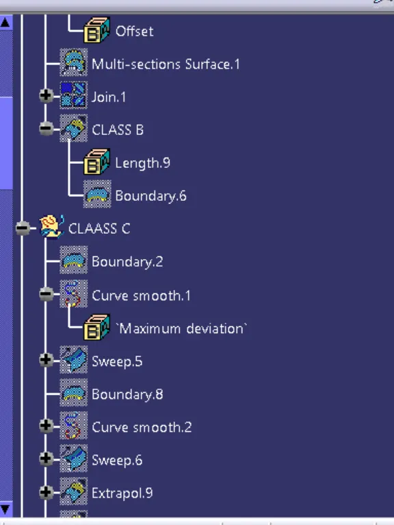
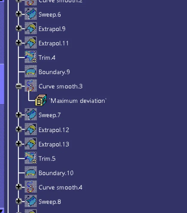
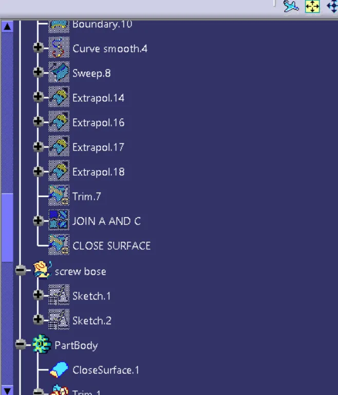
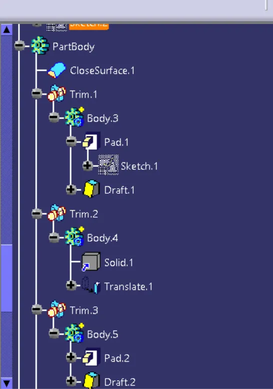
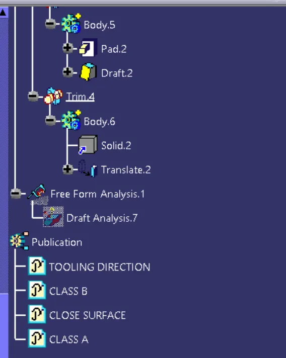
For designing tp RIBS AND SCREW BOSS, we need to create SOLID BODY , from the given class A
CLASS A : It is the given input .
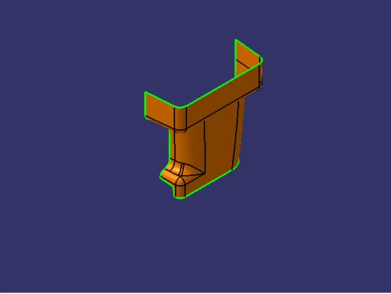
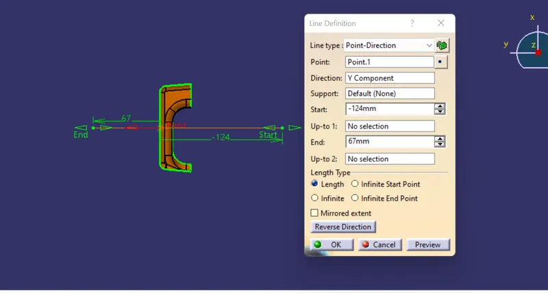
TOOLING AXIS: It is the direction along which core and cavity moves, as in the case of DOOR HANDLE, we can able to see the component along y direction , so , from Y direction , we will make the tooling axis.
DRAFT ANALYSIS : We will check , that our tooling dirction is clearing our part with 3 degree draft or not .
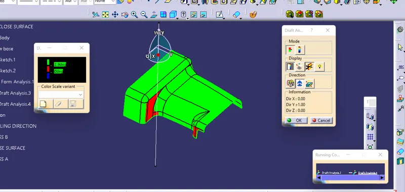
so, here we saw that at some suraface , draft is not clear , still neagative draft shows, it means taht our given CLASS A has not good.
CLASS B : we will take offset from the given class A , BY 2.5 mm and we will repair those patches, which are not offseted well.
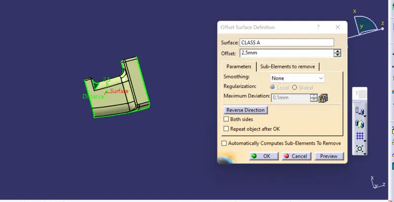
repair class b
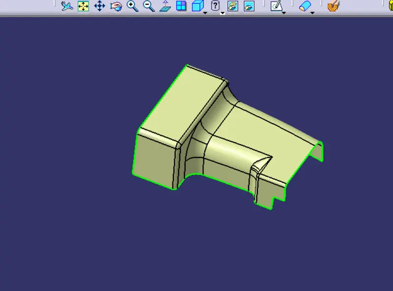
CLASS C: It is used to join the class A and Class B suraface , we will take sweep command with 3 degree draft direction
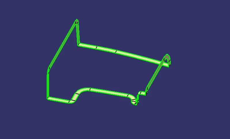
close suraface : trim the class B and join a and c
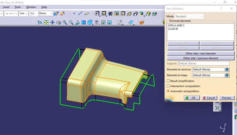
make a closed body , through CLOSE SURAFACE METHOD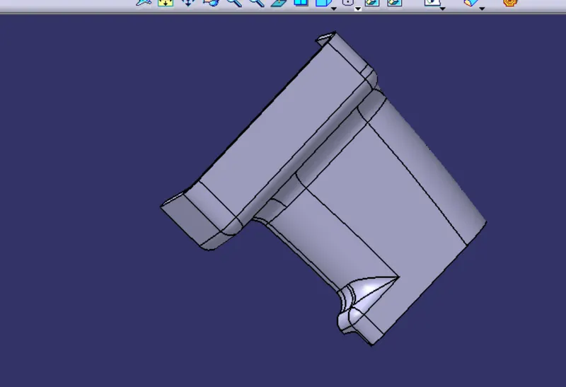
draft analysis :
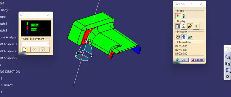
As , after draft analysis of solid body , still not clearing our component with 3 degree draft , due to curavture of given CLASS A.
NOW, WE WILL CREATE RIBS
Ribs : Ribs provide a means to economical stiffness and strength in molded parts without increasing overall wall thickness.
Ribs also facilitate:
1. Locating and aresting components of an assembly
2. providing alignment in mating parts.
3. Acting as stops or guides for mechanisms.
For creation of ribs design, involves 5 main issues
1. THICKNESS
2. HEIGHT
3. LOCATION
4. QUANTITY
5. MANUFACTURABILITY
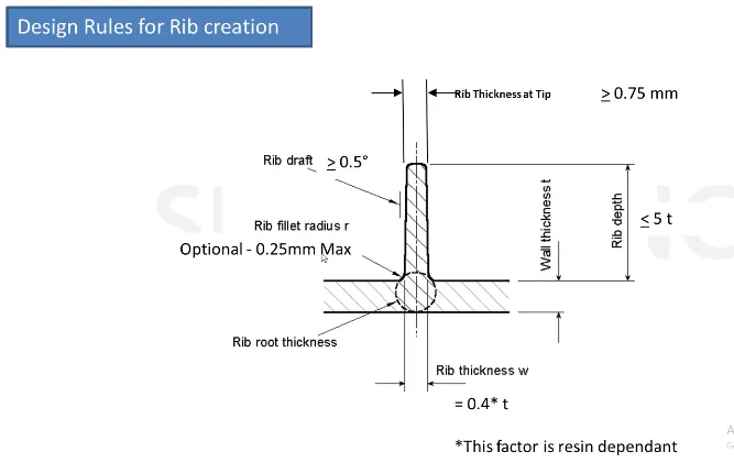
STEPS TO CREATE Ribs
1. draw a line as a sketch for rib
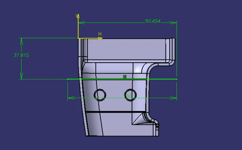
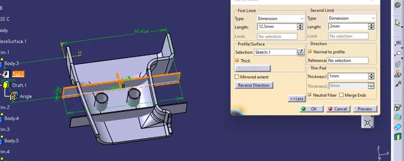
2. pad it for a height of 12.5 mm
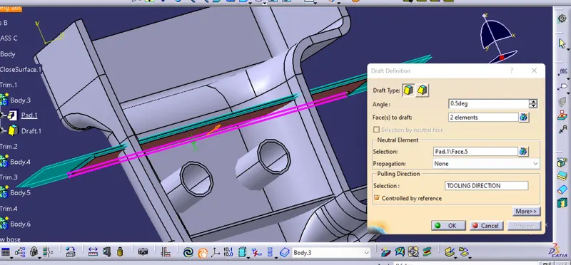
3. provide a draft of 0.5 degree
4. apply boolean to union trim with the main door handle closed body
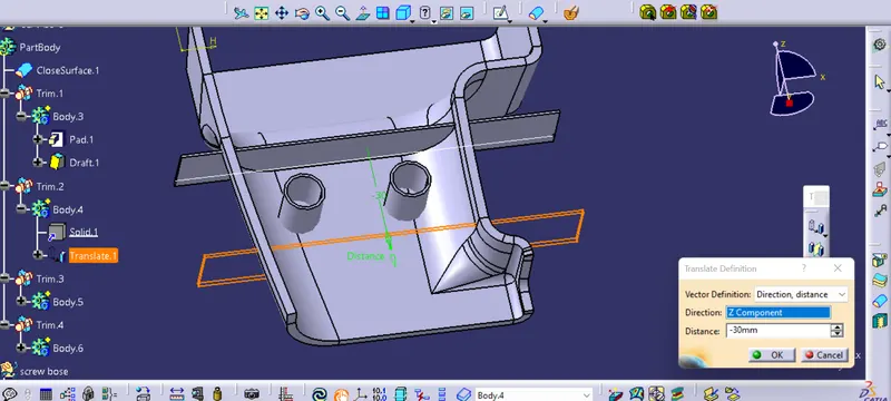
5. to make another rib, MAKE ANOTHER DUMB SOLID BODY BY COPY ORIGINAL RIB and PASTE SPECIAL to Main part body and just translate that with some distance , with TRANSLATE OPTION in the PART WORKBENCH
SCREW BOSS : Bosses find use in many part design as points for attachment and assembly . The most common variety consists of cylindrical projection with holes designed to recieves screws , threaded inserts or other type of fastening hardware.
To reduce stress concentration and potential breakage , bosses should have blended radius instead of sharp edge.
Screw bosses are mainly used for temporary joint.
General Guidelines for Bosses:
- Draft - 0.5 degrees on the walls of boss
- Thickness - Typically 40%* of the nominal wall at the base.
- Height to Diameter Ratio - 3:1
- Radii - 0.25mm maximum radii.
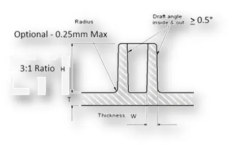
steps to create screw boss
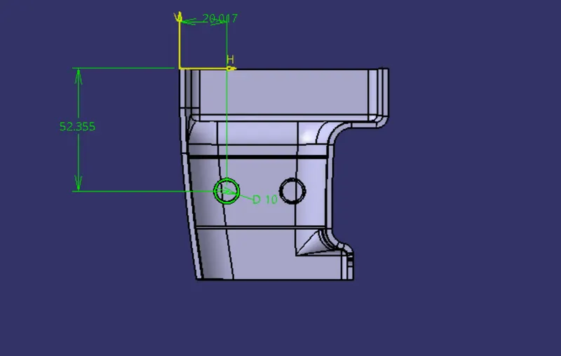
1. create skectch as circle
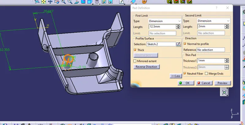
2. pad
3. provide draft with 0.5 degree along tolling direction
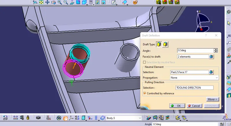
4. just using boolean , we need to union trim with main closed body.
draft analysis : 0.45 degree we will check for screw bosses and ribs
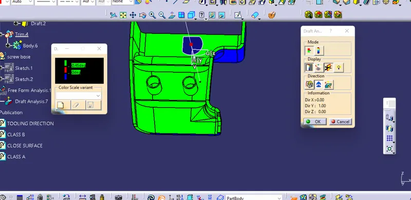
hence , our 0.45 degree draft has clear our screw bosses and ribs.
views :
isometric views
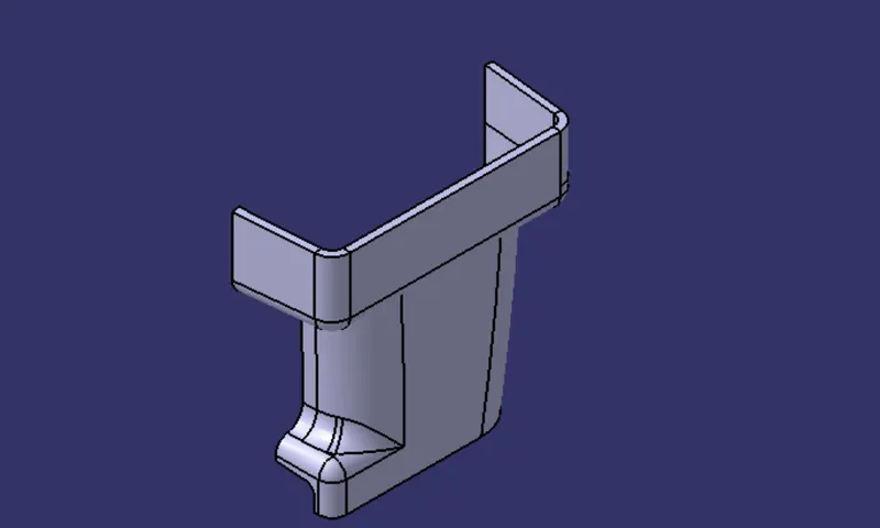
front view
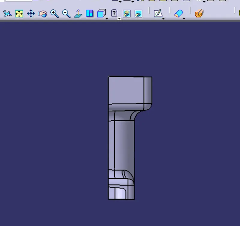
side view
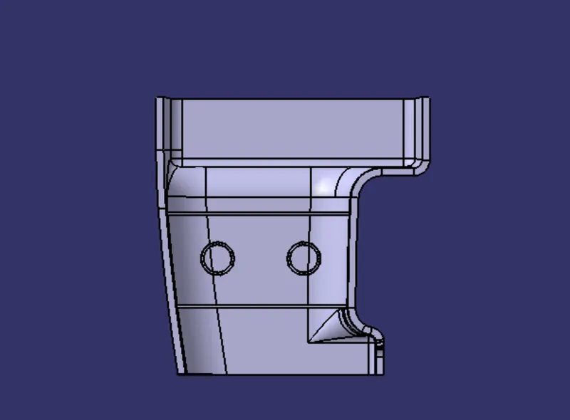
top view
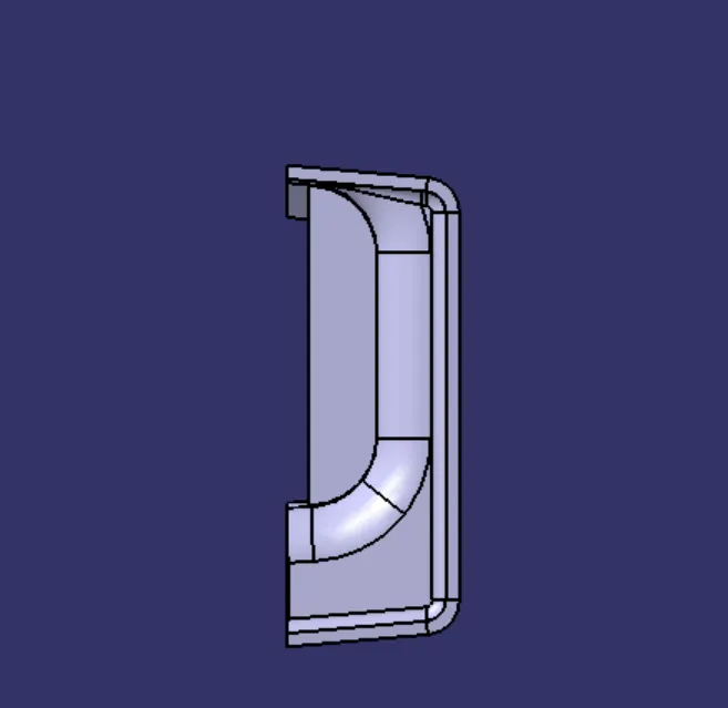
CONCLUSION
, HERE , i have designed the screw boss and ribs, from the given CLASS A input.