Week 9 - Attachment Feature Creation (Ribs & Screw Boss) - Challenge 1
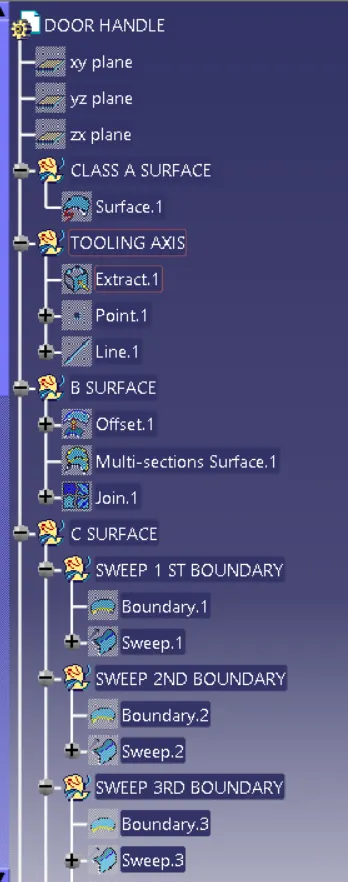
First of all,we have to create a solidbody from the given A surface.Then we need to apply the ribs and screw bosses in them.So for creating the solidbody,the primary step is to make the Tooling axis
CREATING THE TOOLING AXIS
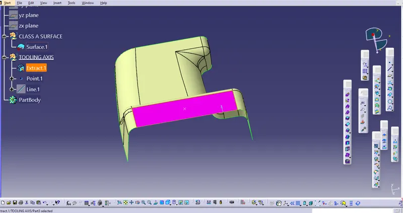
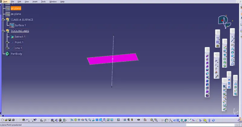
For creating the tooling axis,first we have to check for a flat face.So,I selected the pink highlighted area as the flat face.Make a point on the surface and create a line using point-direction with respect to Y axis.Then our Tooling axis is formed
PERFORMING THE DRAFT ANALYSIS
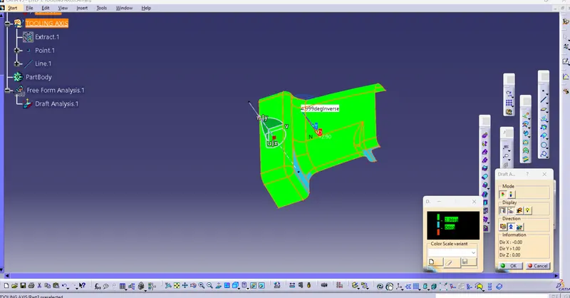
The next step is to perform the draft analysis.For doing draft analysis
- Click on Insert -> Analysis ->Feature draft analysis
- Put the compass into the Tooling axis,make sure that compass is perfectly alligned
- Click anywhere in the surface(if it is appearing green in colour it means the draft is cleared)
- Perform "Analysis under running point"to know the angle of the surfaces
In these case the draft is not clearing,In some surfaces 1 degree angles are appearing.So we have to make a report to the Class A designer about the draft.
CREATING THE SOLID/CLOSED SURFACE
First we have to create the B surface.For creating the B surface,just offset Class A surface to 2.5mm.
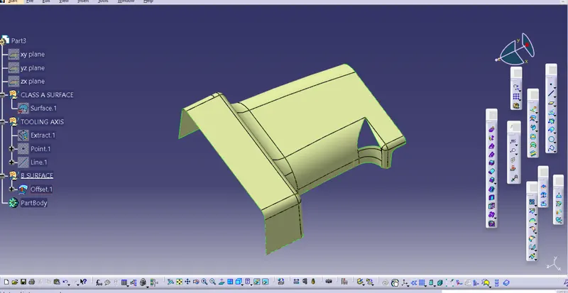
Then we will gain the surface with these patch.We have to close the patch using the Multisection command.The fill option is not recommended.After doing the Multisection command,we have to join the Class B surface with the filled surface using Multisection
After this, hide the B surface and unhide the A surface.Then we have to perform the sweep in the A surface.Here I am performing the sweep with reference surface with 90 degree angle.If we do the sweep with the draft direction,then it will not clear the draft analysis beacause of the problem that mentined earlier.
Sweep all the surface and join the C surface with the A surface.After that,trim A+C Surface with the C surface.Before trim make sure that both the surfaces will intersect each other.
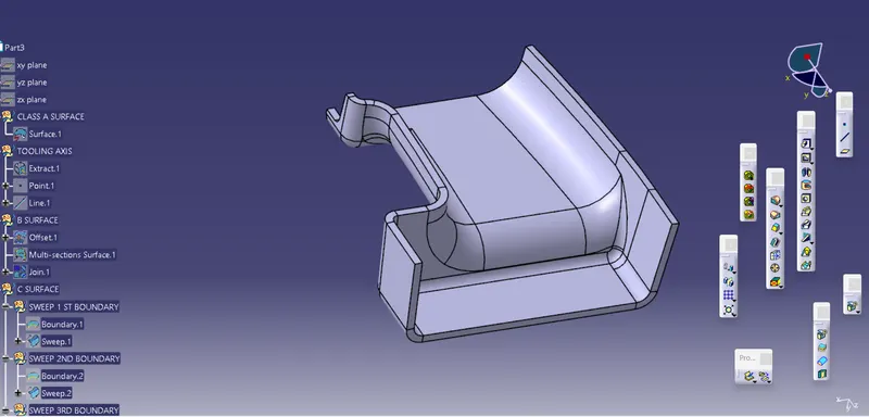
After that make it a closed body after entering the part body
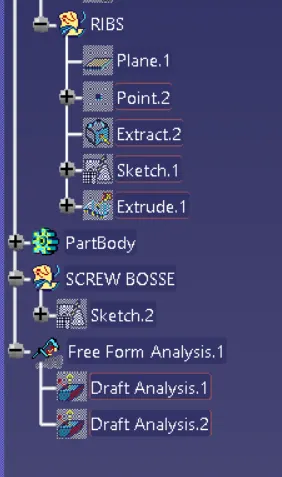
After creating the closed body,we are going to create the ribs and screwboses.First we are going to create the ribs.
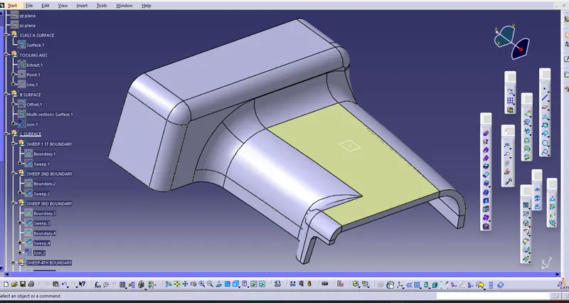
For creating the ribs,firstly exract a surface from the top.Create a point on the extracted surface.After that create a plane on that extracted surface using the refernce xz plane and the the point that we created.And draw the sketch
The engineering features that are applied in the creation of the ribs are:
- Thickness = 2.5mm
- Height (5t) = 12.5mm
- Fillet = 0.25
- Draft angle = 0.5
So inorder to create the ribs,draw the sketch on the plane and extrude it and give the specified thickness.The next step is to give the draft for the ribs.
Before giving the draft,define the thickness in the part body.Steps for doing the draft are :
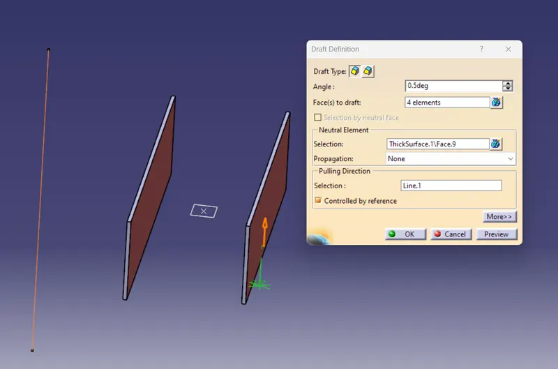
- Click on the draft
- A dialogue box as above shown will appear
- Give the angle 0.5 degree
- Select the four elements that are parallel to tooling axis represented as brown in colour
- Select the tooling axis as the pulling direction and give OK
After this,define in part body and union trim the extra body of the ribs that are made.
Design calculations for screw bosses are:
- Hole size=5.2mm
- Outer diameter=8.2mm
- Fillets=0.25mm
- Height=12.5mm
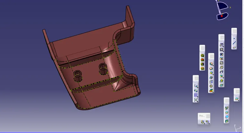
For making the screw bosses draw the sketch in the plane,extrude define it in the part body.Apply the draft and the fillets.
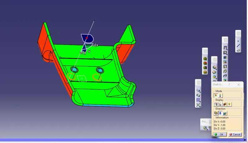
The draft analysis done on the final body