Week 9 - Attachment Feature Creation (Ribs & Screw Boss) - Challenge 1
AIM : To Create the rib and Screw boss for the Drill Handle considering the design rules mentioned .
Detailed report explaining the tooling axis creation :
- The direction in which the core and cavity or mould open and closes is called the tooling axis direction.
- Use the Join or Boundary command to check the connectivity of the surface and ensure that there will be no gap between the surfaces and then define the tooling axis direction .
- First the Flat surface of the given surface is extracted for creating the tooling axis in y direction .Then created a with the point and direction along y axis
Creating the tooling axis based on the Bisecting method :
Intersect the class A surface with the XY Plane of the Axis system and then draw two lines separately o each sides and then draw another line usig bisecting method as line type and select those two lines and the point that we created o the extracted surface . This is our required Tooling axis .
Detailed report explaining the Draft Analysis :
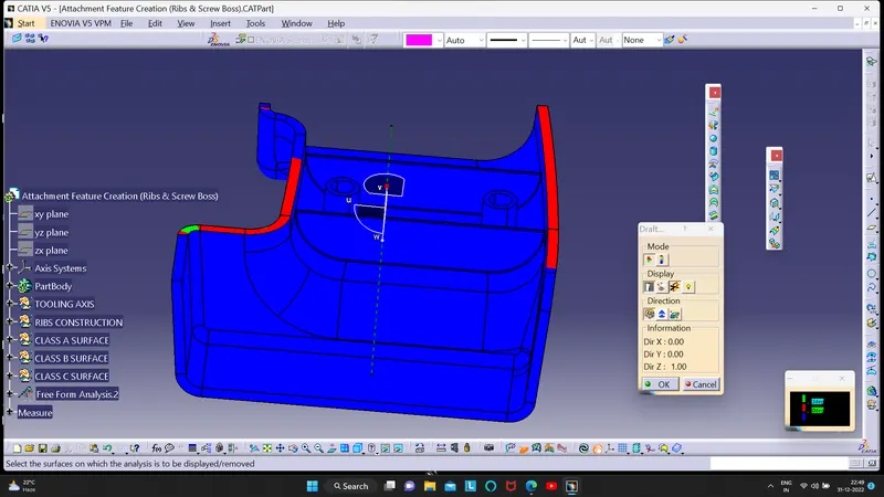
- Follow steps : Go to insert> analysis> feature draft analysis
- Place the compass on the Tooling axis that is created using bisecting method .
- Select the lock symbol to fix compass along with tooling axis .
- Click on the surface then various Color codes will be appeared and Draft angle is applied . Make sure that the surface is within the permissible limit of the draft values. The surface should be green and nominal draft value should be 3deg .
- Thus the draft analysis on the class-A surface is successfully performed.
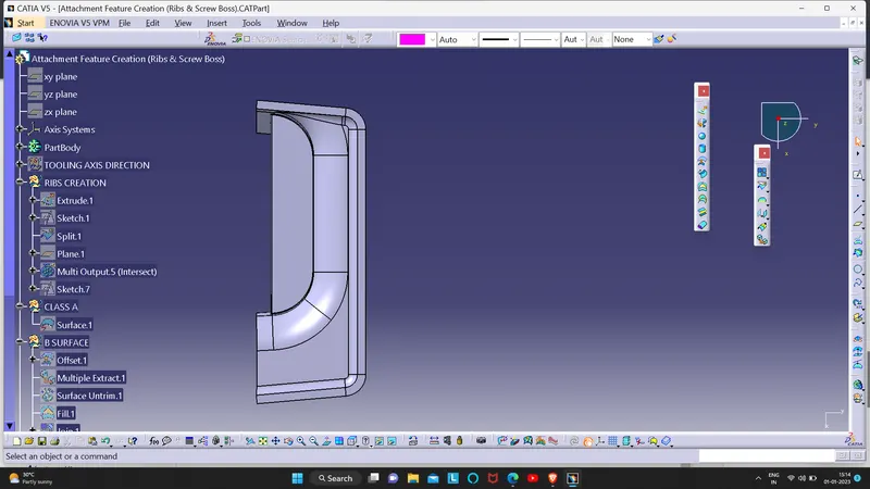
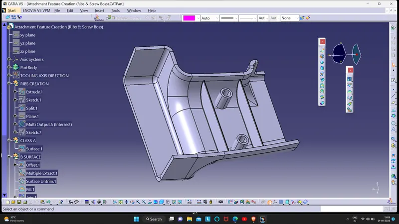
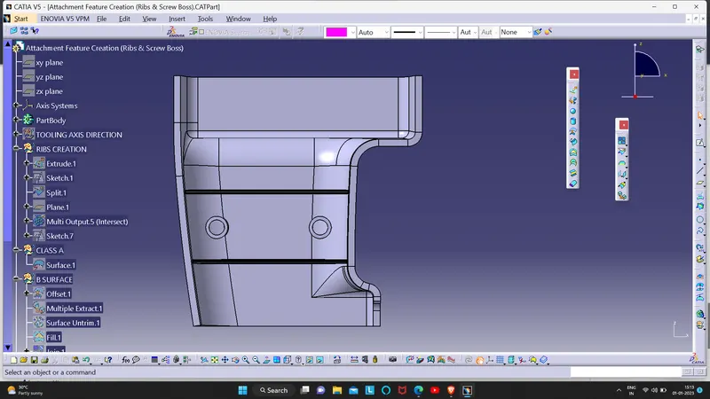
- Screenshots of the completed design in various orientations (Isometric, Front, Side, and Top View) :
ISOMETRIC VIEW :
FRONT VIEW :
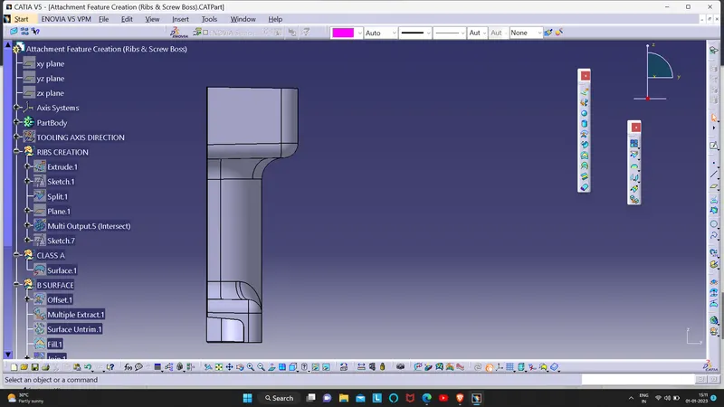
SIDE VIEW :
TOP VIEW :