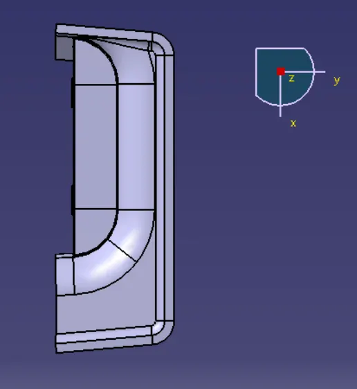
Week 9 - Attachment Feature Creation (Ribs & Screw Boss) - Challenge 1
STEP 1: DOWNLOAD CLASS A SURFACE
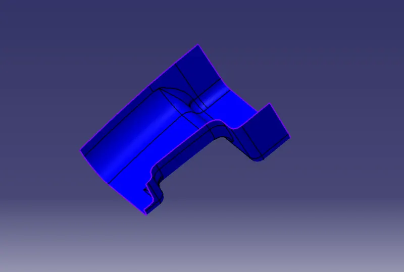
STEP 2: CREATING TOOLING AXIS
- Visually check first in each direction x,y, and z axis for best tooling direction
- So y direction is the best direction for tooling axis.
- Creating a point over a flat plate and making a line in y direction.
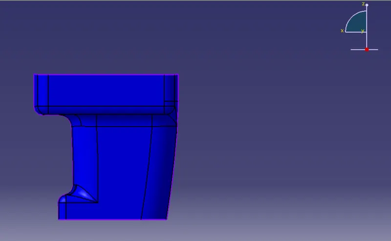
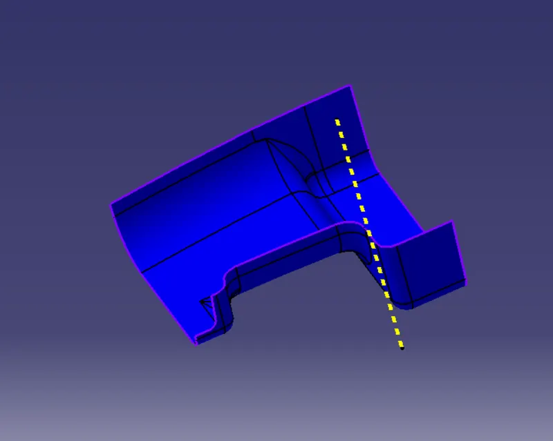
STEP 3: CREATING B SURFACE
- Simply using the offset the class A surface by 2.5mm
- After that use extrapolate, multiple extract, multisection command to fill the gap.
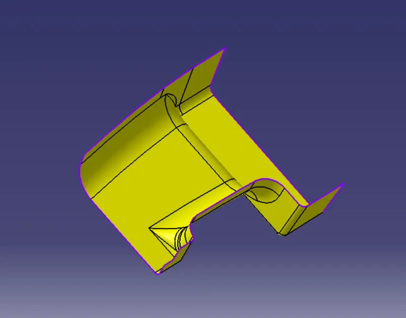
STEP 4: CREATING CLASS C SURFACE
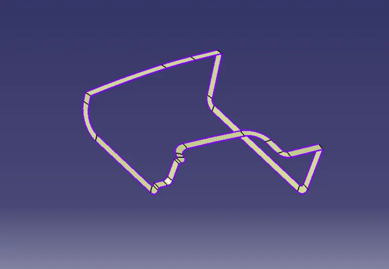
STEP 5: FINAL JOIN AND TRIM
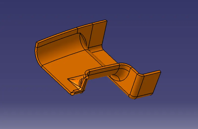
STEP 6: CREATING RIB
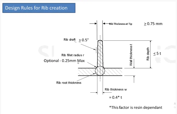
- Create a sketch of the ribs for the closed body using the axis system.
- Then pad this sketch and the height is 2.5*5. Next use uniontrim with the main body, get ribs for the body.
STEP 7: CREATING SCREW BOSSES
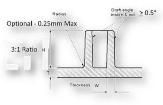
General Guidelines for Bosses:
- Draft - 0.5 degrees on the walls of boss
- Thickness - Typically 40%* of the nominal wall at the base.
- Height to Diameter Ratio - 3:1
- Radii - 0.25mm maximum radii.
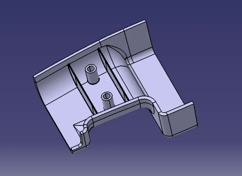
STEP 9: FINAL OUTPUT WITH RIBS AND SCREW BOSSES ON DOOR TRIM
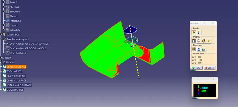
STEP 10: DRAFT ANALYSIS OF CLASS A SURFACE
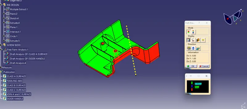
STEP 11: DRAFT ANALYSIS OF THE FINAL DOOR HANDLE
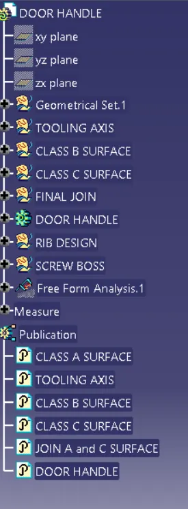
TREE STRUCTURE
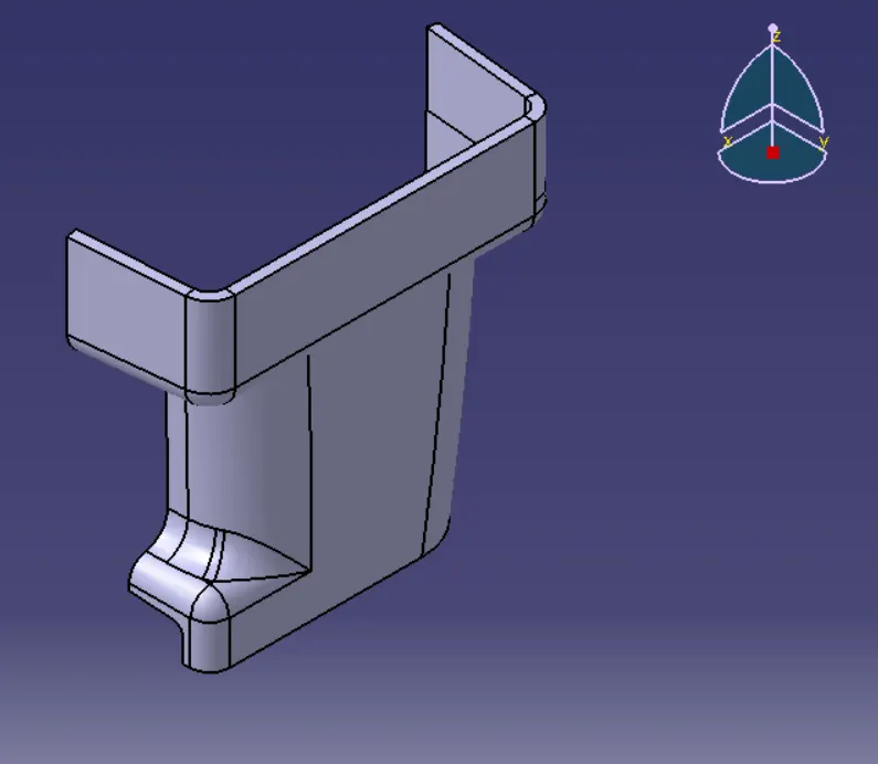
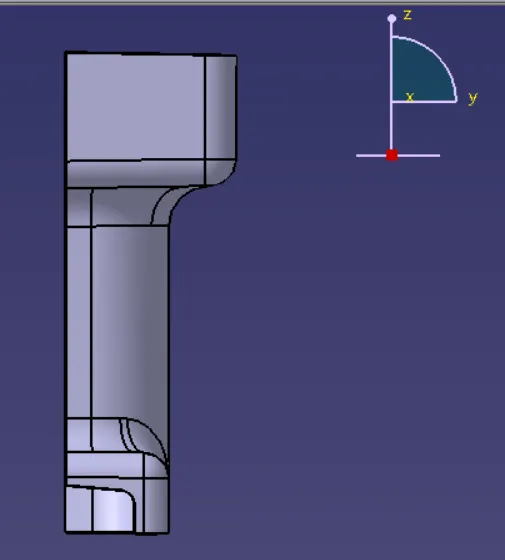
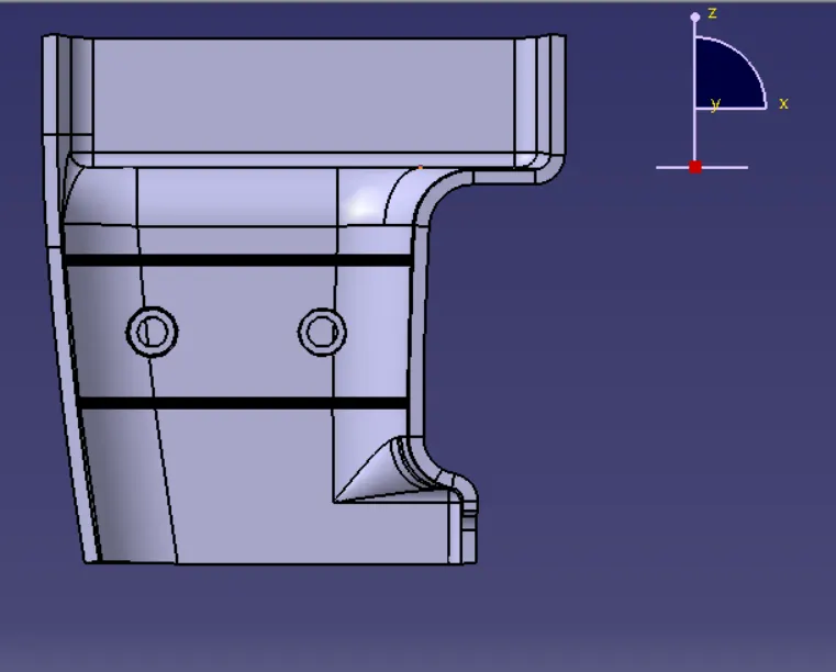
Screenshots of the completed design in various orientations (Isometric, Front, Side, and Top View)
ISOMETRIC VIEW
FRONT VIEW
SIDE VIEW
TOP VIEW