Week 9 - Attachment Feature Creation (Ribs & Screw Boss) - Challenge 1
DOOR HANDLE
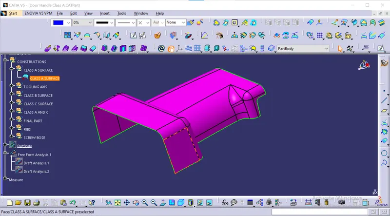
Creation of tooling axis
for the creation of tooling axis we need to check the part in all views ,for in which view it clears the maximum flat surfaces.
front view
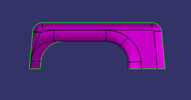
top view
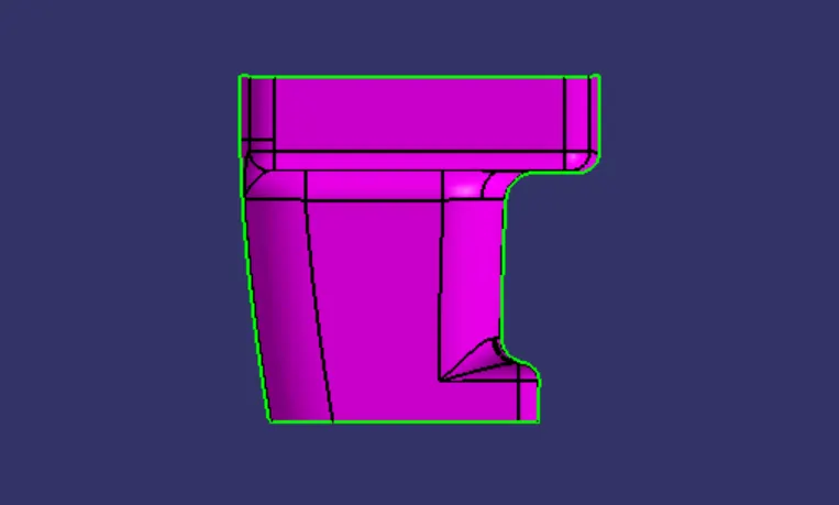
side view
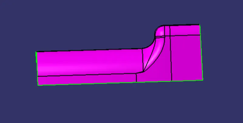
after checking all the views (front view, top view, side view) in the top view it clears maximum flat surfaces as shown in the above figure
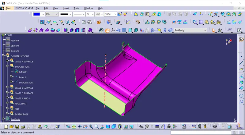
for the creation of tooling axis we need to extract the flat surface as shown in the above figure after that we need to create a point on the middle of the surface as shown in the above figure after that we need to create a line which is normal to the extract that we have created as shown in the above figure.
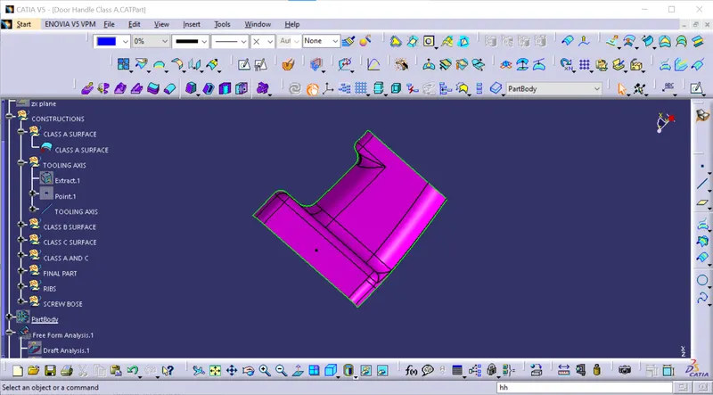
after creation of tooling axis we need to check the tooling axis by clicking on normal view as shown in the above figure wheather it clears all the flat faces or not as shown in the above figure.
Draft analysis on the class A surface
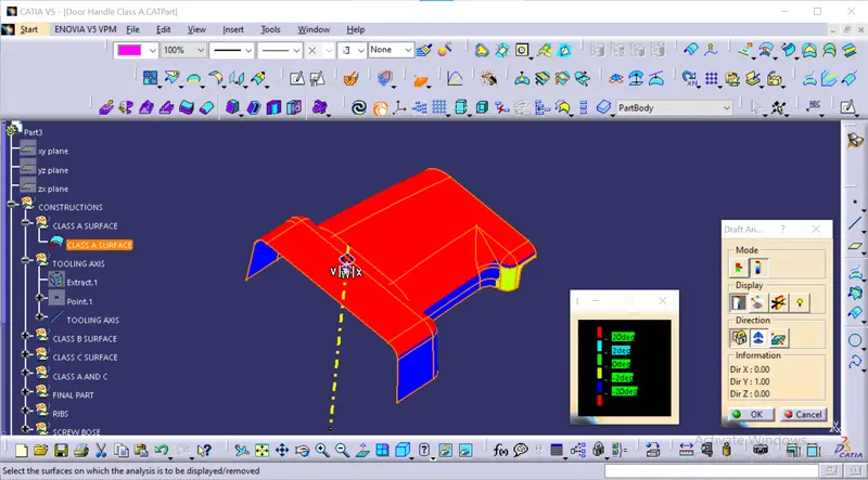
as shown in the above figure we need to do the draft analysis after creation of the tooling axis after that we need to go to the insert tab after that need to go to the analysis tab then need to click on the draft analysis command after that need to click on the axis system then need to place the axis system on the tooling axis as shown in the above figure then need to click on the part for the draft analysis as shown in the above figure.
Class A surface
Class B surface
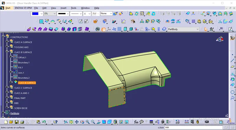
class B surface as shown in the above figure.
Class C surface
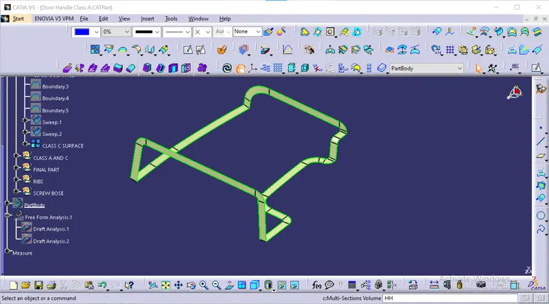
the above figure shows that class c surface for the creation of class c surface we need to click onn the boundary command after selecting the class A surface after that need to click on the sweep command with respect to the reference surface with angle of 90 degrees to the class A surface as shown in the above figure.
Class A & C
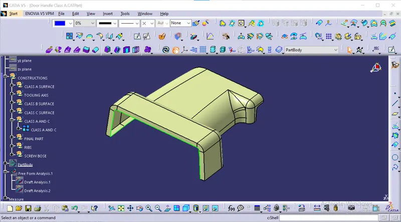
from the above figure it shows that the combination of class A and class C surface by using join command with a clearance of 0.001 as shown in the above figure.
Final part
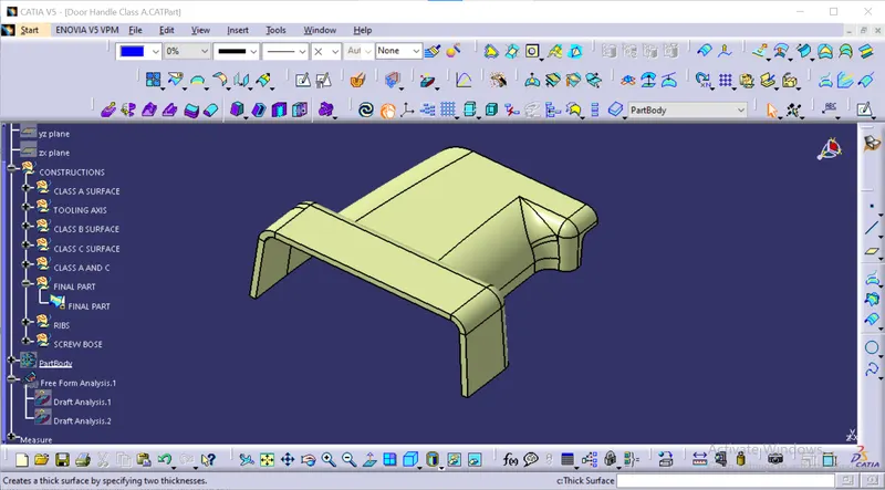
it is the combination of class A and C surface with class B surface by using trim commmand.
Checking of open boundaries
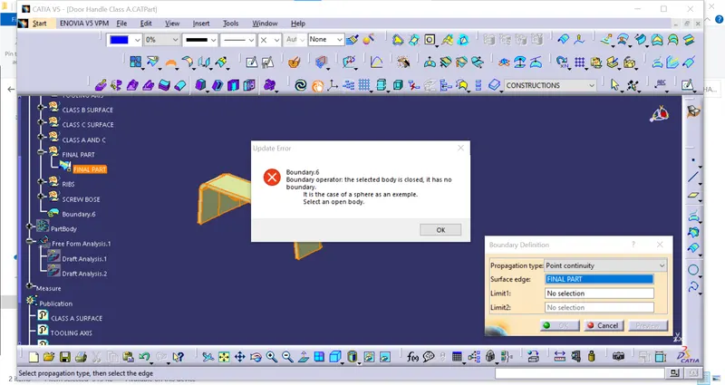
after creation of final part we need to check the part wheather it contains any open boundaries or not by using the boundary command .
Close surface
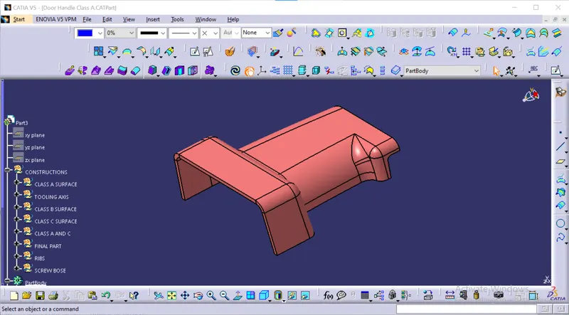
the above figure shows that the creation of close surface by using close surface command for that we need to define the partbody after that we need to go the part design after that go to the close surface. then we need to click on the part that we have created after clicking on ok then the close surface is created. as shown in the above figure.
Ribs and screw boss
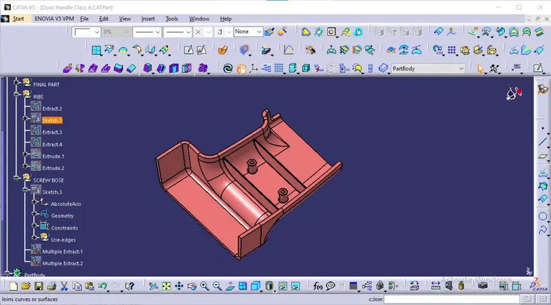
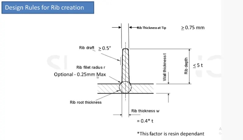
for creation of ribs and screw boss we need to use some calculations for creating the ribs and screw boss
for ribs
for screw boss
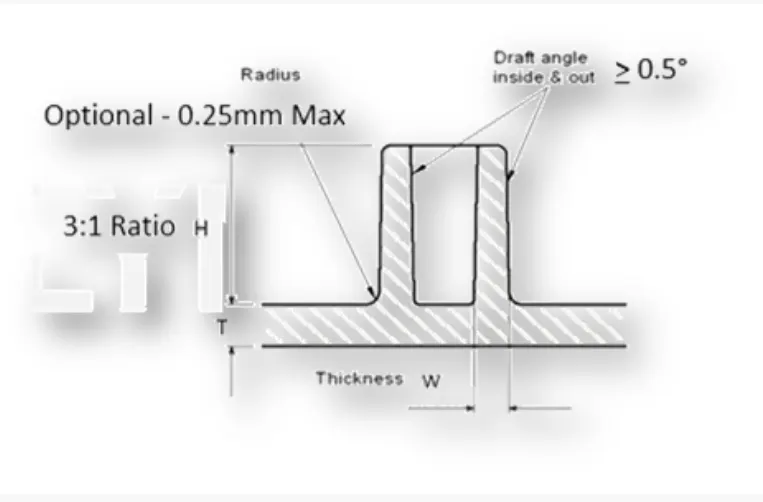
General Guidelines for Bosses:
- Draft - 0.5 degrees on the walls of boss
- Thickness - Typically 40%* of the nominal wall at the base.
- Height to Diameter Ratio - 3:1
- Radii - 0.25mm maximum radii.
for the creation of ribs and screw boss we need to use some design rules for creating of the ribs and screw boss as shown in the above figure .
Tree structure
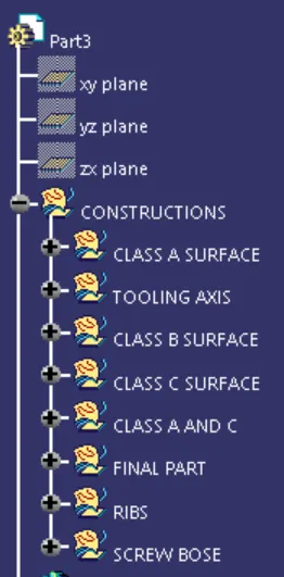
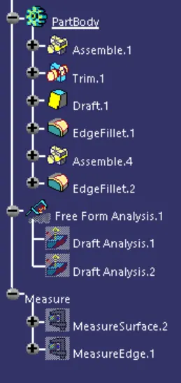
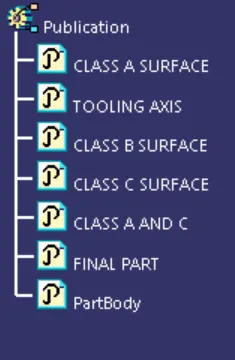
we need to maintain the proper tree structure for proper undeerstanding of the design that we have created.
Draft analysis on final part
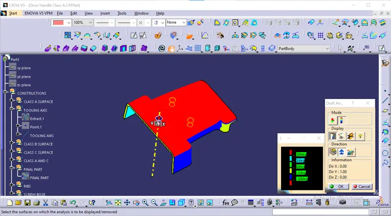
after creation of the final part then we need to go to the material mode after that we need to go to the insert tab after that we need to go the the analysis tab on there there is a option called draft analysis . we need to select that draft analysis command after that ther is window is opened inn the catia screen as shown in the above figure after that need to select the axis system and the need to place it on the tooling axis after that we need to lock the movement of the axis system by using the lock button. after that we need to clisk on the part after that the part colour is changed according to the draft angle of the part and also the criteria table as shown in the above figure . after that we need to click on the ok button after that the draft analysis is done on the part that has been created.
after completion of draft analysis then we need to the define the part body after that we need to go to the close surface command in the part design from the above figure .in draft analysis we should know the proper draft angle of the designed part. as shown in the above figure there are two modes are there for the criteria of the draft angle that we have created after that there are some more options are there called compass etc., these are also used for the checking of the draft angle as shown in the above figure.