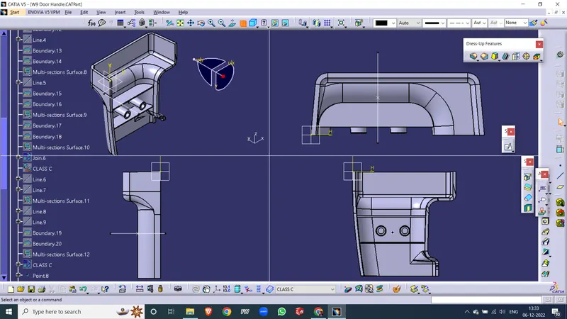
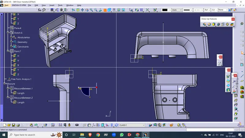
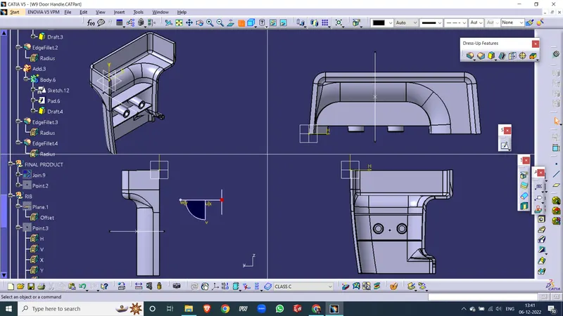
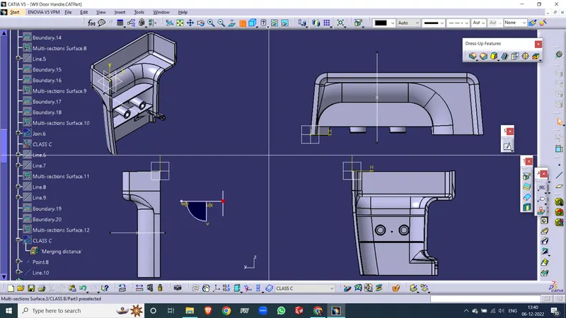
Week 9 - Attachment Feature Creation (Ribs & Screw Boss) - Challenge 1
Tooling Axis creation:
It is described as the path in which the mould/core and cavity open. Selection of the path of the tooling axis relies upon on the ease at which elements can be without difficulty ejected.
By analysing the issue the most without problems ejectable route is someplace shut to the Z direction,(might be inclined to it) so we have made a layout on the YZ aircraft of Axis System) to create a bisecting line thinking about the two faces which would possibly be tough to be tooled.
DRAFT ANALYSIS
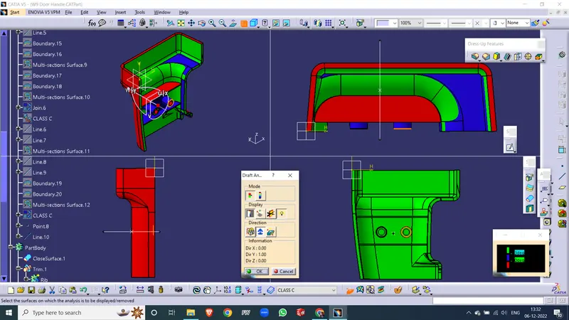
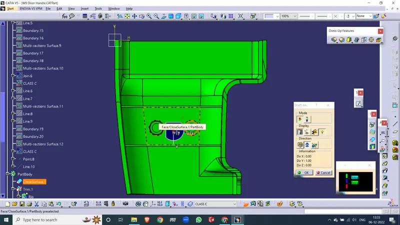
Draft evaluation is a approach used in sketch to test whether or not the element created in CAD is manufacturable based totally on the draft circumstance applied. The primary motive in the back of the draft evaluation is the phase manufactured ought to be without problems eliminated from the mold. It additionally offers an thought of the draft attitude from the tooling direction. Here we are giving a tooling course in order to eject the aspect effortlessly from the tool. The perfect draft perspective given in car industries for plastic elements is three degrees.
Some of the components where draft analysis is done are hood, fenders, roof, side doors, etc.
The draft evaluation is an vital device as it helps the consumer to analyze the draft on quite a number surfaces, the draft evaluation in CATIA makes use of the colour codes for the identification of the draft. Each shade has its personal that means for the minimal draft bad draft and beneath draft.
The draft evaluation toolbar affords two modes for evaluation of the draft, first is the speedy evaluation which essentially has three hues for inspecting GREEN, RED, AND BLUE on the different hand different choice is the full evaluation mode which permits a few extra important points into the draft and is used in the complicated elements like the instrument panel, etc. In the above challenge, we have used the rapid evaluation made for inspecting the draft here. Now, deliver the compass and align it with the tooling axis and click on the lock button in the dialog box.
CREATING THE RIB
Ribs are thin wall protrusions that extend perpendicularly from a wall or plane. They are usually found in clusters offering support to a plane that would have otherwise been too thick, but can also be stand-alone support for a single wall. They are commonly used to provide additional support and strength to a part. Thickness and location are essential to rib design.
First, the base surface where the rib has to be created is extracted using the Extract command. A positioned sketch is created and the profile for the rib is drawn.