Week 8 - Challenge 4 - Bumper
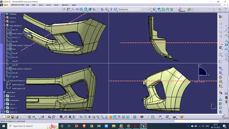
Tree Structure ..
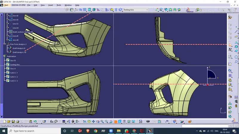
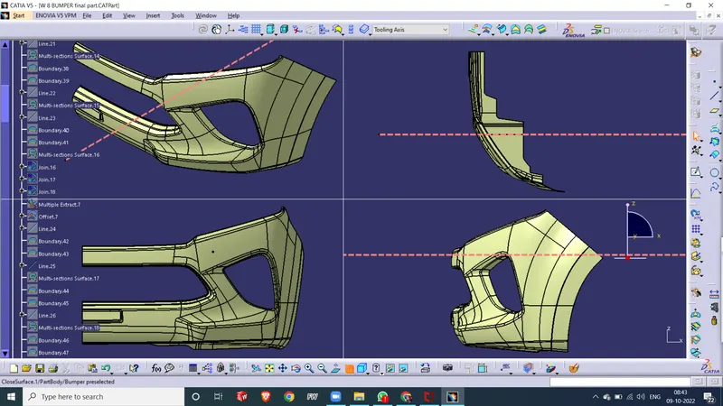
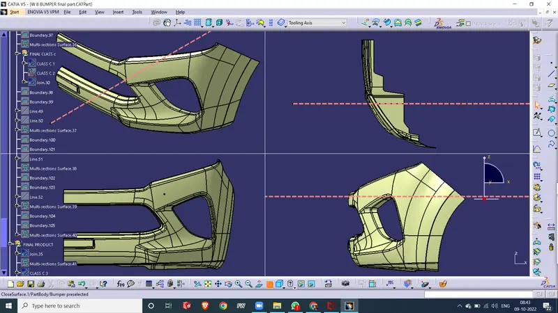
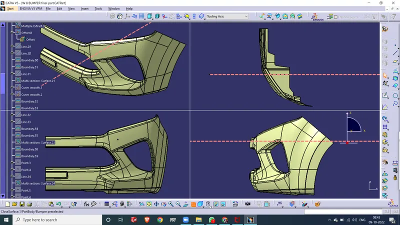
It is very obvious that to analyze draft analysis we need to draw a Tooling axis first, then respect to tooling axis we need to discover that every area of the component should be at 3deg, so that component could made in core and cavity block easliy.
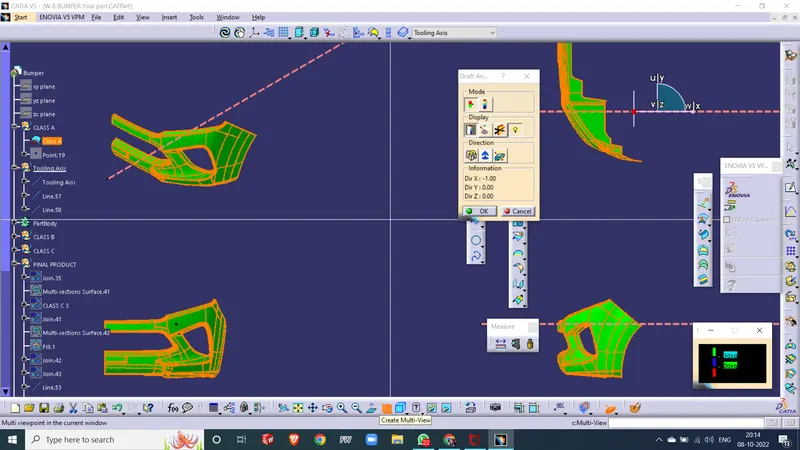
Tooling Axis: At this point, i have seen the part of the component from top view which is going to be in Cavity block, then i desided a point from where ejection of the component could be done easily, i created a line , when we see a line from top view we can mostly see every side of the cavity part of model, when i have done draft analysis of the component , it turns into green which i have set it to 3 deg , this shows that tooling axis is correct and when there will be molding of component from block and cavity there will be no damage or defect of the component .
in molding maching arrangement we use tooling Axis as the direction to push the component out from the Block and cavity mold, basically block and cavity are two different block parts .
Draft Analysis :-
Draft Analysis allows the user to analyze the part of the component for proper draft angle, this is aplicable in 3 D part modeling to creat Draft analysis for any 3 D part file , we have to select the tooling Axis as the pull direction , and we can change the pulling direction .
Draft Analysis of Class A Surface In CATIA :-
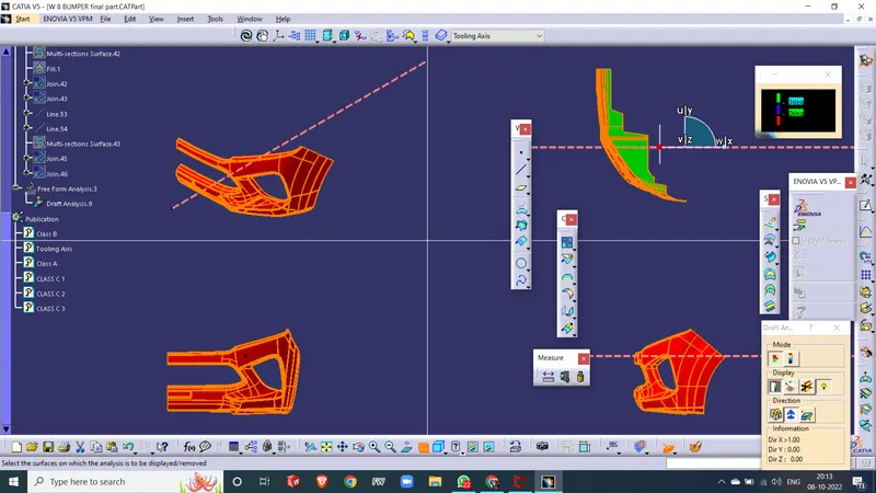
it convert the Model from basic to different color identification, with the help of this we can easily understand about angle of degree of each perticular surfaces represented by different colour identification, surfaces where it comes RED it shows with respect to pulling direction that red surface is at -tive direction, surfaces which are Green with respect to pulling direction it have positive angle under 3 degree or more but atlest 3 degree.
if there is any red color in the surface then create another tooling axis for correct draft angle color green.
Class B Surface :- Offseted part of the class A surface is called Class B Surface. Mostly it not visible. It is created by Offseting Class A surface at a distance of (thickness) 2.5mm ,3mm etc. Here I created Class B Surface on 3mm from Class A Surface.
Class C Surface :- The Class C surface is the back side of a part of a surface that is permanently covered by another part.