Week 9 - Attachment Feature Creation (Ribs & Screw Boss) - Challenge 1
OBJECTIVE:Create the rib AND Screw boss for the Drill Handle considering the design rules
RIBS: Ribs are thin protrusions that extend perpendicular from a wall or plane to provide added stiffness and strength. Designers commonly try to increase the strength of a part by making its walls thicker. Unfortunately, walls that are too thick are subject to warpage, sinking, and other defects.
Tooling Axis:- The direction in which mold opens or Core and cavity get separated, is called the Tooling axis.
Phase 1:- In phase 1 we import Class A surface in Catia. That Class A surface may be in the different part surfaces, so we join them using JOIN Command in CATIA. For confirmation of joining we use BOUNDARY command, If boundary shows no error then we go for phase 2.
Phase 2:- In Phase 2 we create Tooling axis of the product then we do draft analysis of it.
STEP-
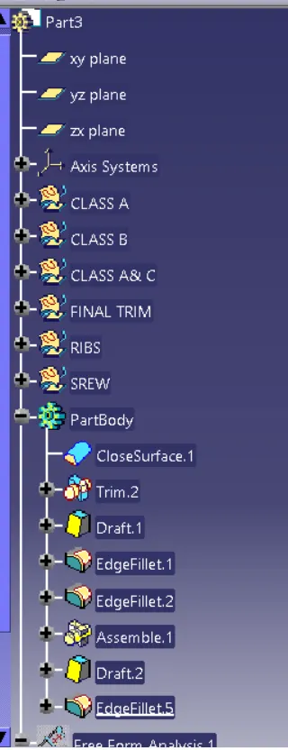
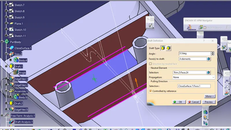
Giving draft to the ribs from four sides of 0.5 deg
STEP-
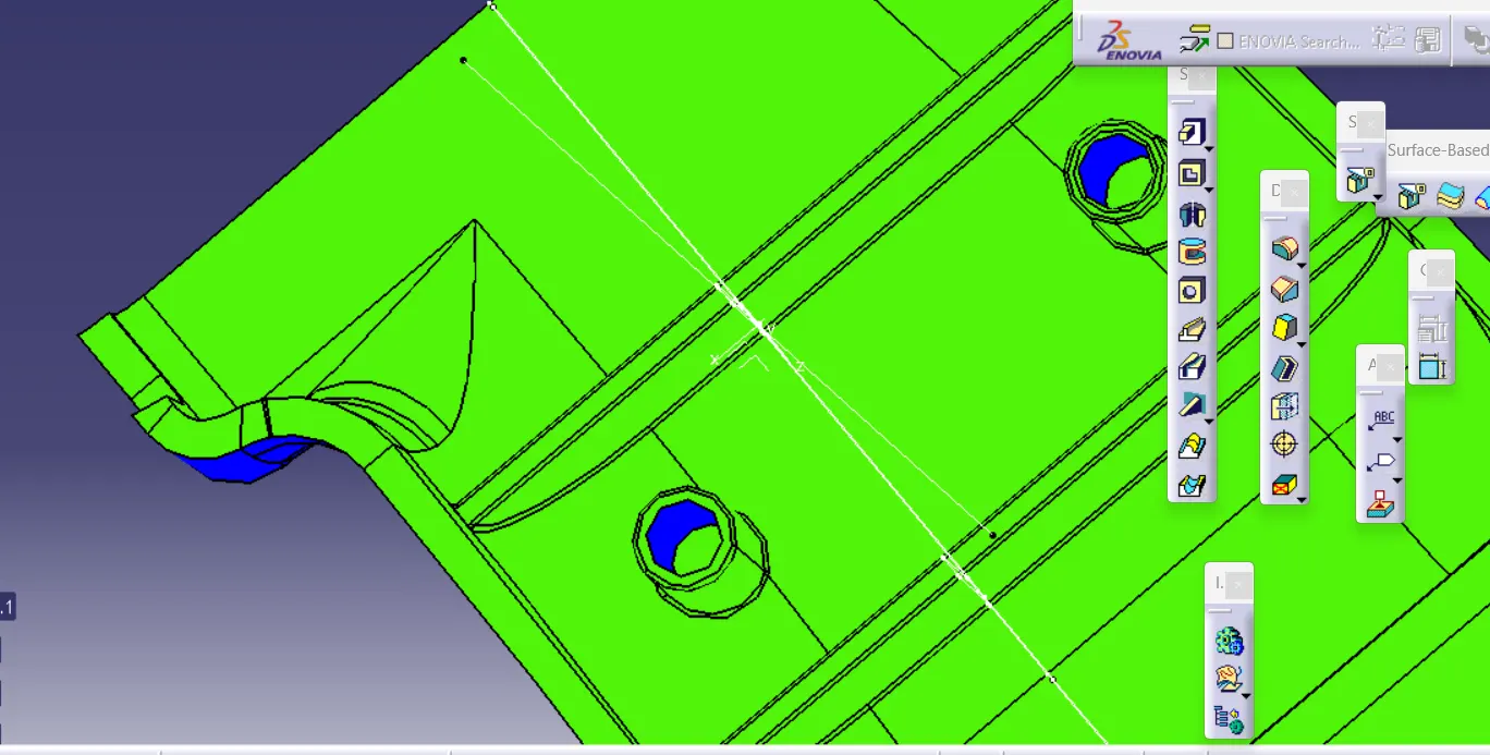
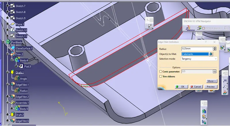
Assemble the Rib part body inside the main part body and give edge fillet to all faces of rib of 0.25mm
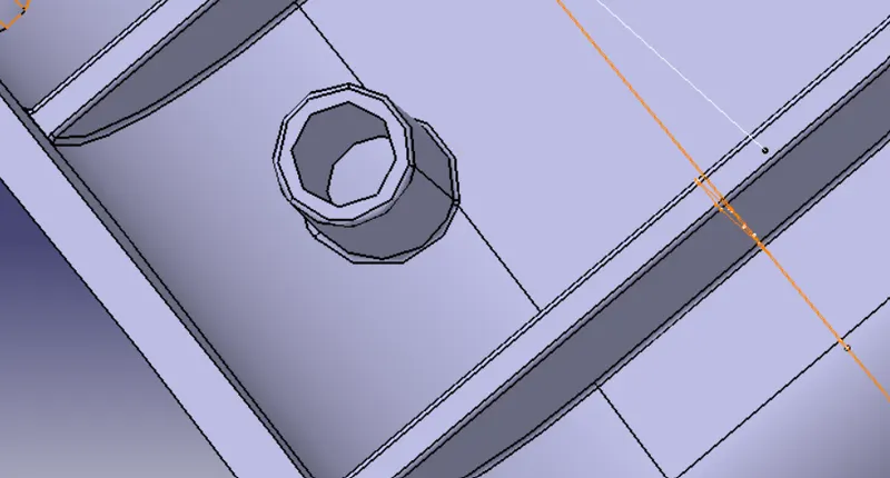
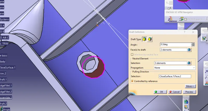
STEP-
Creating Ribs
height/width(mm)=3:1
width=12/3=4.1 (width should be >3)
STEP-
Creating intersection between the reference plane in XY direction and component part body
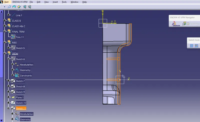
STEP-
Checking for proper dimensions according to the design rules
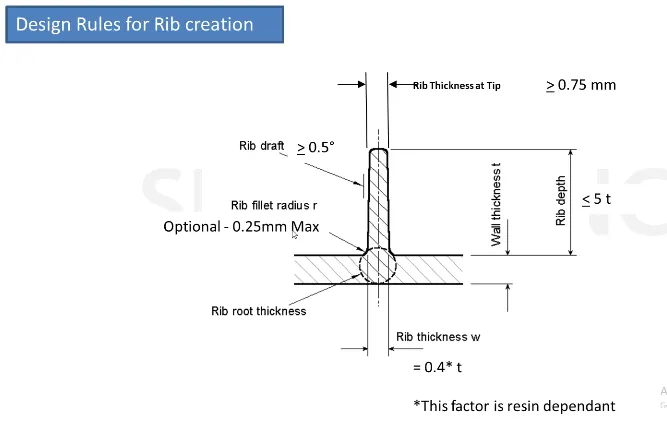
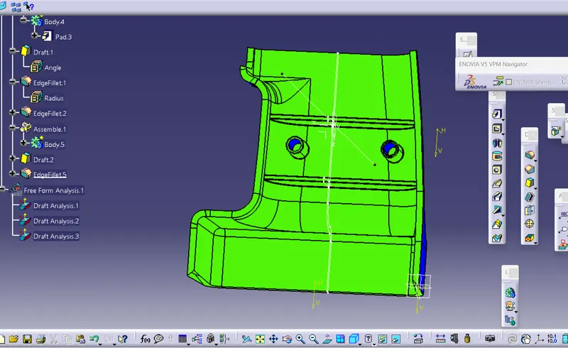
DRAFT ANALYSIS
Go to INSERT-ANALYSIS-FEATURE DRAFT ANALYSIS and move the compass towards the tooling axis and chnage the range to 0.45deg
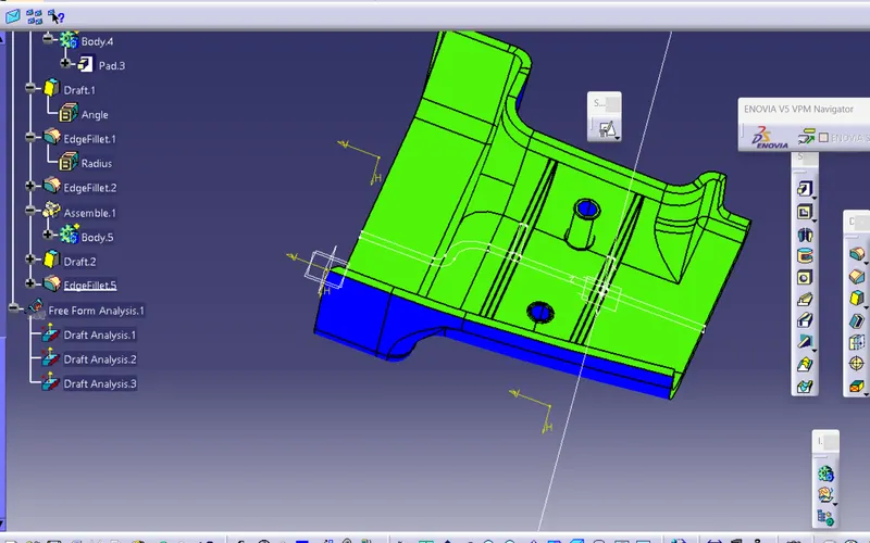
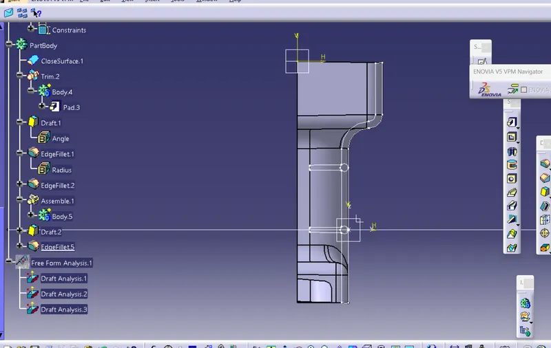
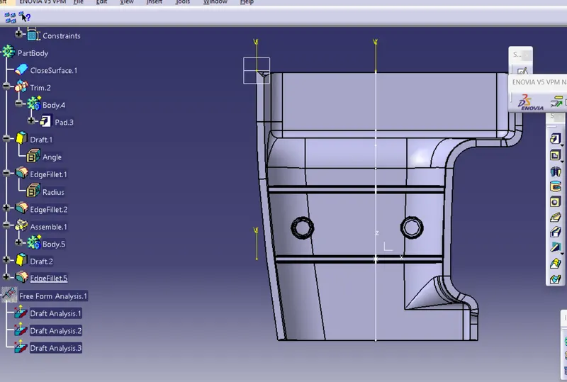
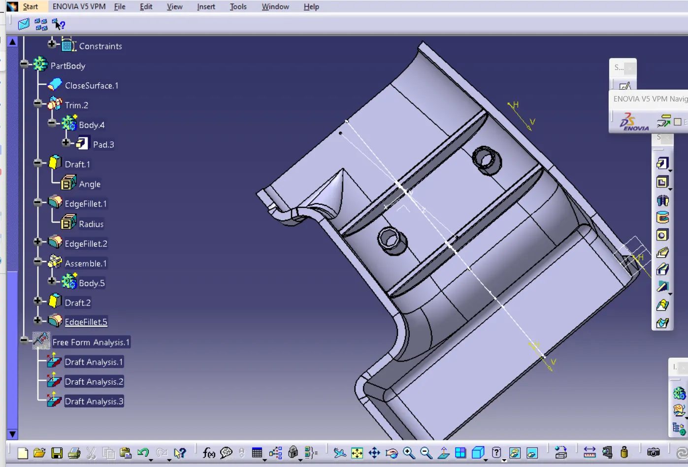
PART BODY