Project 3: Roof Modeling
CAR ROOF DESIGN AND REINF.....
Introduction An automobile roof is the portion of an automobile that sits above the passenger compartment, protecting the vehicle occupants from sun, wind, rain, and other external elements. Under the styling surface that is seen from the outside, there are many other structures under the roof that contribute to its strength and stability. The number of such reinforcement structures/supports differ with respect to the size of the vehicle. They are primarily installed on flatter areas of the roof to enhance strength. These are the Front Roof Rail, Rear Roof Rail, Centre Roof Rail, and Bow Roof Design which are given Mastics and spot-welded to roof flanges & ditch areas and improve NVH value by increasing the strength of the roof using mastic sealants
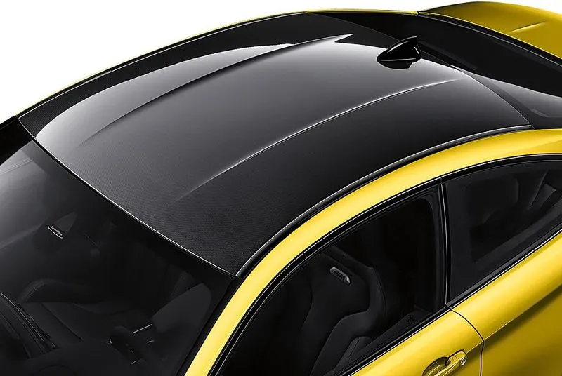
DESIGN CONSIDERATION
1. ROOF BODY FLANGES
2. FRONT AND REAR RAILS
3. BOW ROOFS
4. REINFORCEMENT ROOF CENTER
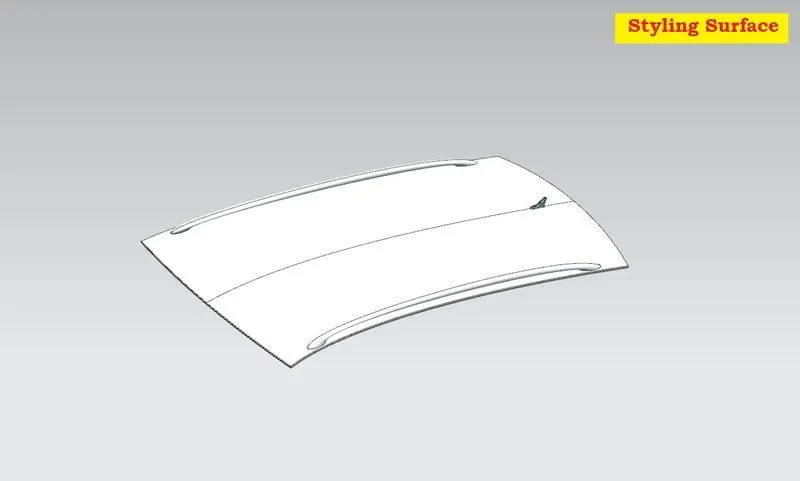
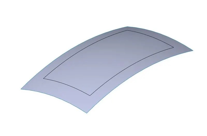
STYLING SURFACE AND EXTERACTED SURFACE
The styling team has provided the solid dump outer panel from that we are extracting the surtout excessary reinforcements like Ditch area, Front Roof Rail, Bow Roof Rails Centre Roof and Rear God Rool
STYLING SURFACE
EXTERACTED SURFACE
Design a Ditch Area for Outer Roof Panel:
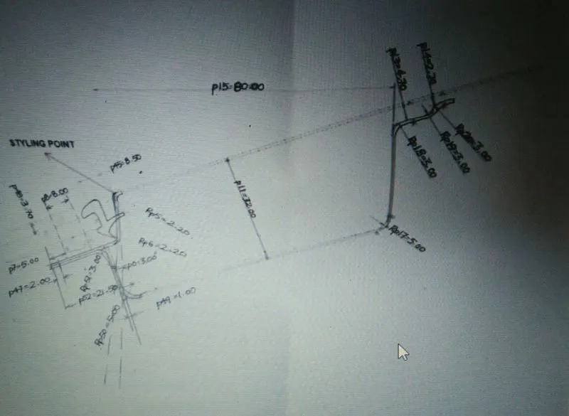
Styling team provided the master section for the roof ditch area, front roof rail and rear roof rail as per the parameter of visibility criteria, head room clearance and other important parameter dimension like fitment of windshield, sealant rubber etc. All these data are well calculated in the planning stage to design the peripheral component accordingly. Thus, here designing is done just to replicate those input data considering engineering parameters which should be feasible for manufacturing. Master section of front and rear section.
1. Front Ditch Area:
From THE dump solid part class A surface is extracted and ditch area are developed considering the parameter specified in the following master section. Flange of around 15mm created with the law extension command, comer relief at rear flanges and positive draft more than 3 degree considering for the drawing operation process. Overall thickness of sheet metal consider 0.75mm throughout.
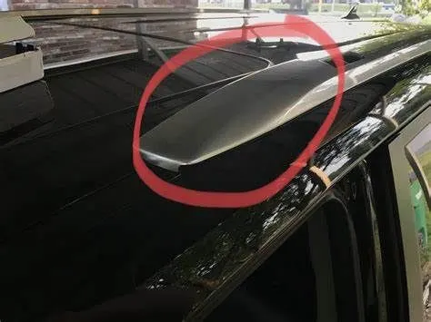
Front Roof Rail:
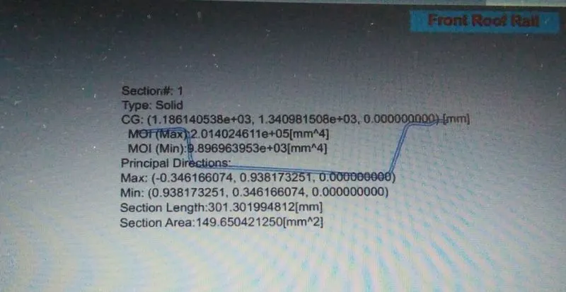
The front rail underpins the rooftop external shell at the front end. It is mounted with support rooftop rall fortification on the two closures. The rails are furnished with embosses to improve the strength over length and the rail is associated with the external board utilizing mastic sealants on one side and the other joinery is spot welded
Sheet metal thickness: T=1mm
Emboss height: 2 <3T
Flange length: 13.2> 3T+R
Radius: (R-3mm and 5mmm)>T
Rear Roof Rail:
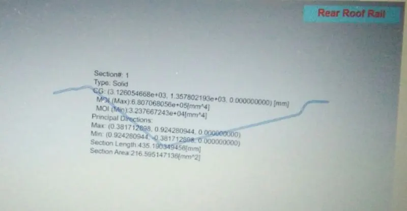
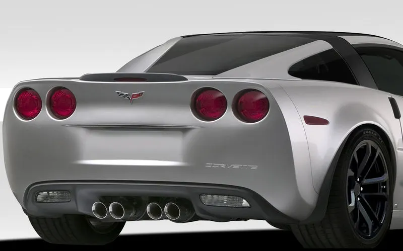
It is the support which is joined to the Back Door and the Body Side Outer and the inner panels. It is also usually made from Body Side Outer scrap and therefore the thickness of the rail is 0.65 mm. Similar to the Front Roof Rail design, we have to take into consideration the rear Headroom Clearance and the rear visibility criteria while designing the Rear Roof Rail Inputs are taken from the rear master section shown in fig.
Following points are considered
Headroom clearance: 120mm minimum
Sheet metal thickness: T- 0.75mm
Emboss height: 237
Radius (R-3mm and 5mmm)>T
Bow Roof 1:
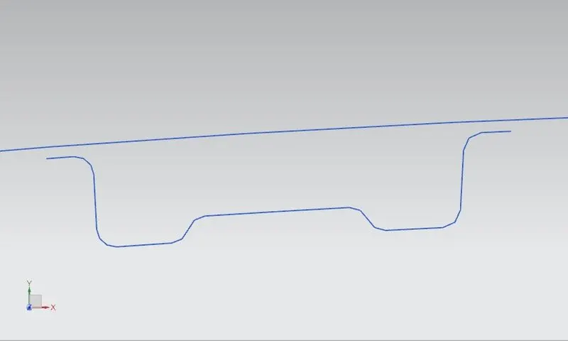
The Bow roofs are given to improve the torsional stiffness and load-bearing capacity of the roof structure The number of bow roofs provided will depend upon the overall dimensions of the roof Longer the roof more the bow roofs are integrated to BIW frame They are attached to the outer panel using mastic sealants. Each mastic point will have up to 80 mm circular effective area. The positioning of bow roofs is done based on curvature study. The heat distortion criteria and snow load criteria are checked to analyse the position of the bows in various conditions The thickness of the Bow Roof is 1 mm and also mastic area has been created
Bow Roof 2:
The Bow roofs are given to improve the torsional stiffness and load-bearing capacity of the roof structure. The number of bow roofs provided will depend upon the overall dimensions of the roof
Centre Roof Rail:
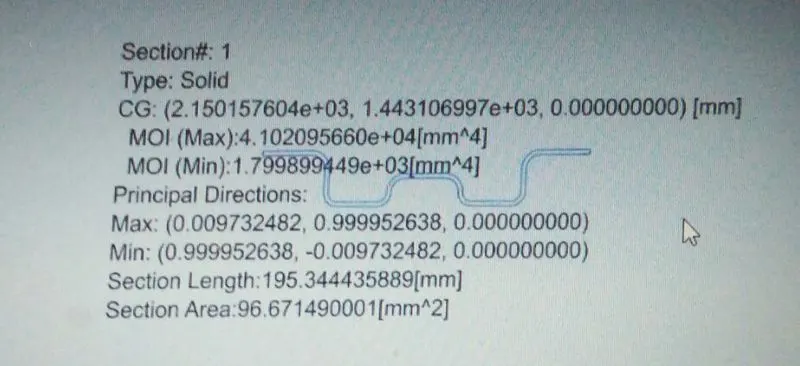
Centre roof rail is provided to effectively support the flat area of the roof as it is more susceptible to failure under the action of the load. Usually, the centre reinforcement roof rail will be placed at the centre of the roof connecting the B pillar support structure which results in added support in the roll-over test. The thickness of the centre bow roof is 1 mm thickness..
bow roof 1
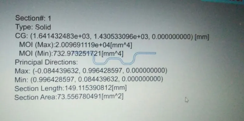
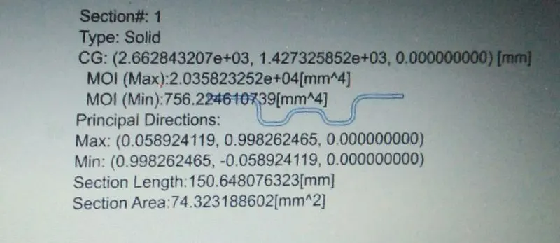
Moment of Inertia (MAX), Imax = 2.009691119 x 10^4 [mm^4]
Moment of Inertia (MIN), Imin = 732.973251721 [mm^4]
Section Modulus, S = Moment of Inertia (MOI)/ Distance between the neutral axis and the extreme end of the object (y)
y= 29.88 mm
For Maximum MOI
, $-(2.00969119 x 10^4 [mm^4])+ (29.88 mm)
Section Modulus, Smax=672.587 mm^3
For Minimum MOI, 5-(732.973251721 [mm^4]) (29.88 mm)
Section Modulus. Smin=24.53 mm^3
Bow Roof 2:
Create an intersection Curve with the help of the plane and select the Bow Roof 1
When the intersection curve has been created and hide the model, we will get this curve shown in below fig
Project the Curve to the XY plane to find the section analysis