Week 1:- Introduction to BiW and Fixtures Challenge
1. What is BIW & define its parts?
BIW (Body in White) is a stage in automobile design or automobile manufacturing in which the sheet metal components are assembled or joined together to form the vehicle structure. The joining processes can be welding, riveting, gluing, brazing etc
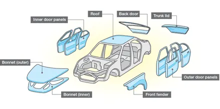
BIW structure Basic Parts in BIW are discussed as follows
1.Body sides The side ward parts of the BIW structure falls into this category
1. Body side Outer:
This refers to the sideward outer parts of the body/frame
2. Body side inner: This refers to the sideward inner parts of the body/frame
2.Under body The bottom/downward parts of the BIW structure falls into this category
1. Front end under frame: This refers to the frame under the front end i.e. under the engine bonnet
2. Main floor:
This refers to the frame under the middle i.e. under the seats
3. Rear end under frame:
This refers to the frame under the rear end i.e. under the boot cabin
3.Clousers The closing parts of the BIW structures such as doors/lids parts fall into this category
1. Front door:
This refers to the parts of front door panels of the automobile
2. Rear door:
This refers to the parts of rear door panels of the automobile
3. Hood:
This refers to the closure door the hood of the automobile
4. Deck lid:
This refers to the closure lid of the deck of the automobile 4.Roof The top covering parts of the BIW structure falls into this category
1. Roof inner:
This refers to the inner side of the roof surface
2. Roof outer:
This refers to the outer side of the roof surface
5.Fender The front and rear fender parts of the BIW structures falls into this category
 ?
?
- 2. what do you understand by BIW nomenclature?
There are several parts involved in BIW structure. These parts are identified or referred using BIW nomenclature.The terms used in nomenclature for referencing parts are as given below:
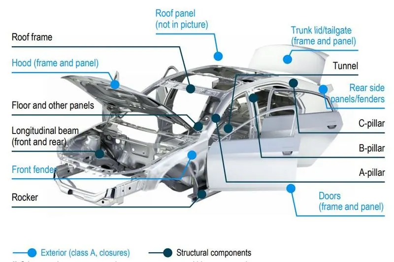
BIW nomenclature Since there is small differences in UK english and US english in the image they are mentioned as seperate. but actually both represent the same part or component from BIW structure.
classification There are two kinds of body structures in use:-
1. Monocoque Body Structure
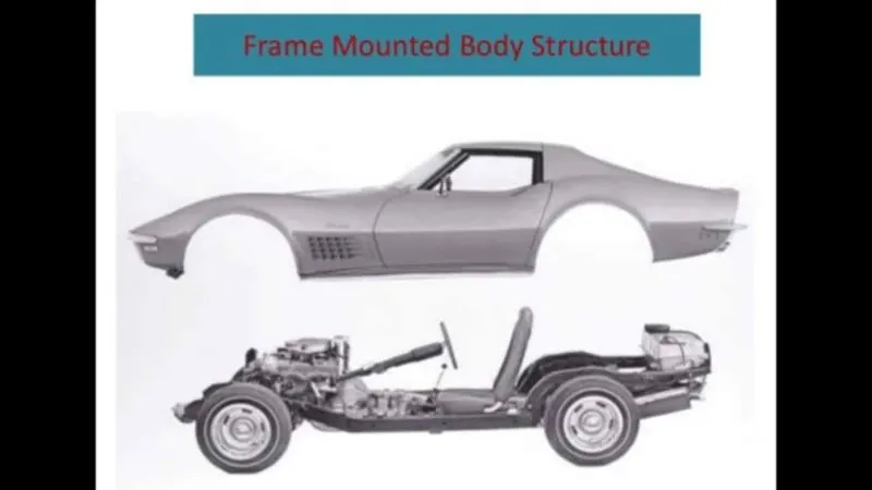
2. Frame mounted Body Structure
Description Monocoque Body Structure:-
In Monocoque Body, Chassis is in built in the BIW itself.
And there is no separate chassis.
Wheels are directly mounted to the BIW with the help of suspension system.
Frame Mounted Body structure :-
In the Frame Mounted system body is mounted on the separate Chassis/Frame
And wheels are mounted on the Chassis not to the body.
Monocoque Body structure
Frame Mounted Body Structure
BIW Structure can be divided into following sub structures:-
› Under Body Structure
› Front End Structure
› Body Side Structure
› Closures
› Roof
All those substructures consists of the following major panels:-
An Under Body Structure :-
Dash panel-provides partition b/w engine and the driver cabin.
FRT floor - provides base for seats.
Raiser - connects front floor to rear floor by providing level difference.
Rear floor - floor on the rear of the car and provides partition from ground and base for rear seats
Rear wheel house
Front End Structure :-
Plenum Panel- a chamber located b/w the throttle body and runners of the intake manifold.
FRT wheel house(Fender)- is an encasement around the frt wheel.
Wing panel - outer most side panel in the front .
Cowl -portion of the body bounded by the front fenders, the base of the windshield, and the rear edge of the hood.
Upper tie bar -upper panel in front connecting the two sides of front structure.
Lower tie bar- lower panel in front connecting the two sides of front structure.
Body side Structure:-
A- pillar - front most support to the roof
B- pillar - second support to the roof
C/D pillar - c- is rear most support to roof in case of two row seating system, it will be third one. D- is the fourth support usually rear side of quarter panel.
Ring panel - a structure panel connecting the rear and front portion.
Quarter panel - rear most panel of a body side structure.
Drip rails / Gutters- an exposed channel applied to the roof over the side windows to direct water away from the windows.
Closures :-
All doors
Hoods/Bonnet -a hinged panel providing access to the engine compartment.
Roof Structure:-
Roof
Headers - structural member above the windshield at juncture with the forward edge of the roof panel.
Bows
Reinforcement component The part which are used to support and provides stiffness and strength to other components of BIW.
3.What is fixture & its types design ?
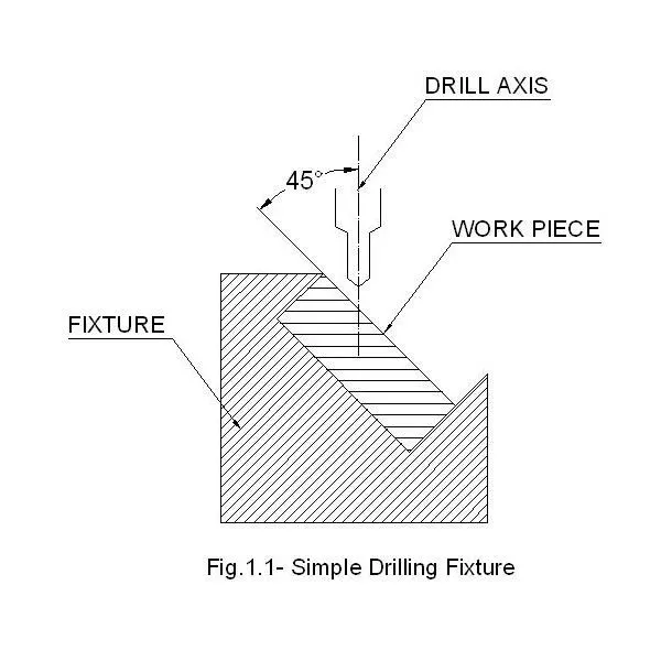
=> Fixture is a holding device which holds the workpiece to be processed.
In general fixtures are designed using 3-2-1 principle.
Further, fixture should firmly hold the work piece without causing vibrations, distortions, stresses in the workpiece and also fixture should not disturb or interfere the processing of the workpiece
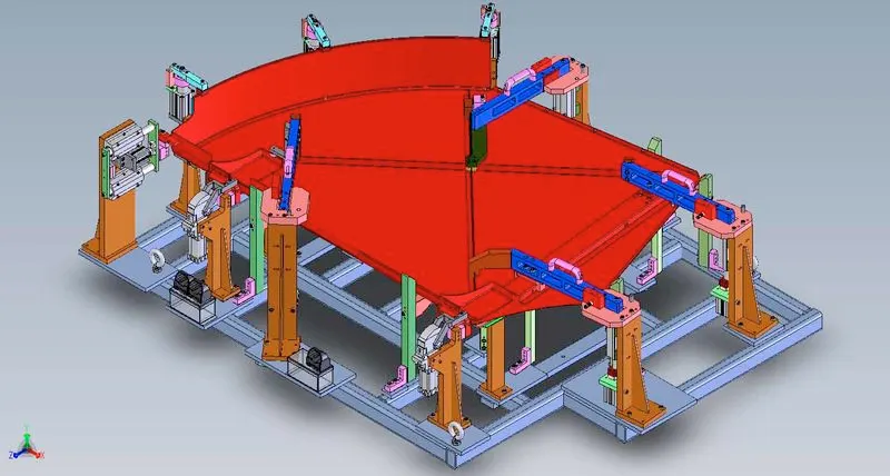
Typical welding fixture Types of fixtures are as follows:
1. Production Fixtures:
These fixtures are used for mass production. Since these fixtures are used for mass production, they should be simple, rigid and hard.
These fixtures should be periodically maintained in regular intervals to avoid errors and repairs.
The design of the fixture should be in such a way that it should be easy to load and unload the workpiece within seconds to increase the productivity of the processing/assembly
2. Preproduction operation fixture:
These fixtures are basically newly designed fixtures for the new products or parts.
These may be complex, manual and heavy based on the application.
These can be referred as the protype fixtures. Once the preproduction operation fixture functions properly, then modifications are made to improve and to make it simple and reliable. These fixtures are used in special cases or during initial or trail stages of processing/production
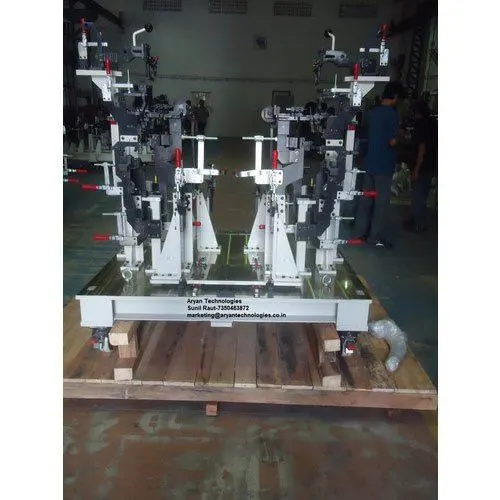
3. Checking fixtures:
These fixtures are used for checking and inspection purpose. No processing is done in these fixtures. These fixtures consist of gauges for checking the dimensions and tolerances and its accuracies. In some checking fixtures, fixtures are fixed and CMM devices check the geometrical accuracies
4. What is the basic principle of fixture design?
The aim of the fixture is to hold the workpiece in the desired angle and location. For a free body we have 12 degrees of freedom they are six rotational and six translational. Six rotational degrees of freedom refers to clockwise and anticlockwise along X, Y, Z axes and six translational degrees of freedom refers to translation in X, Y, Z axes. So the basic principle of fixture design is to arrest or restrict all the 12 degrees of freedom in the desired or required location and orientation Image 4.0: Degrees of freedom
5. elaborate types of biw station?
Tool stations:
The stations in which different tool processing are done fall into this category
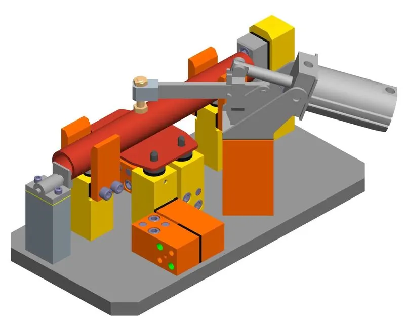
Typical tool station
1. Geo fixtures:
These fixtures are used to find or measure geometrical accuracies.
In these fixtures the pin tolerance of the geo pin should have a closer tolerance of -0.15 2.
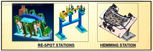
2. Re spot fixtures:
These fixtures are used to re-spotting of missing weld spots or other missing processing were carried out.
These helps in reducing ideal times of the stations in assembly line.
In these fixtures the pin tolerance of the re-spot pin should have a closer tolerance of -0.28
3. Marriage fixtures:
These fixtures are used for inner and outer panel assemblies.
Since the joining of two parts happens in this fixture they are called as marriage fixtures.
4. Framer fixtures:
These fixtures are used for joining roof to the marriage fixture assembly output products.
Since it makes a complete frame to the marriage component it is called framer fixture
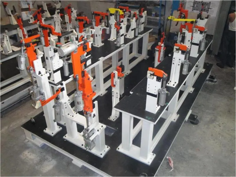
5. Checking Fixtures:
These fixtures are used for checking and inspection purpose.
No processing is done in these fixtures.
These fixtures consist of gauges for checking the dimensions and tolerances and its accuracies. In some checking fixtures, fixtures are fixed and CMM devices check the geometrical accuracies
2. Grippers stations:
A gripper is a holding device which manipulates the object or move the object from one place to another place.
Gripper can be an end effector of a robot. It can be called as end of arm tooling.
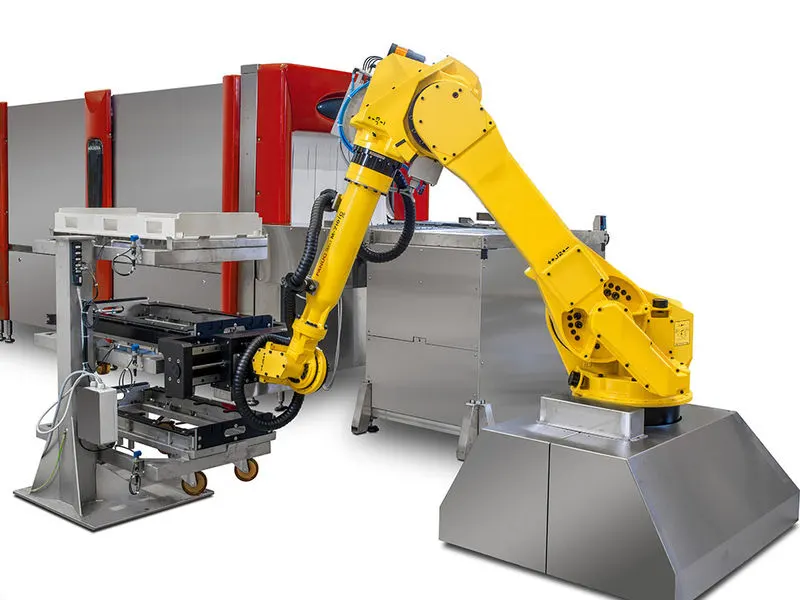
Typical gripping station
1. Material handling gripper:
These grippers are used to handle materials from one station to other station
1. Process gripper:
These grippers along holding they also helps in completing processing.
For suppose when the gripper holds the workpiece and moves along the glue nozzle gluing process will be done
2. Combo gripper:
These grippers consists of the holding equipment and processing tool equipment
. This helps in obtaining combination of holding and processing. Hence these are called as combo grippers
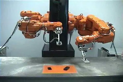
Dual grippers:
These are two sided grippers. This helps in holding two workpieces at a time which saves lot of time in assembly line.
3. Stand stations:
Stand stations are used to hold or mount the workpiece
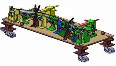
Typical stand station
1. Pedestal stand:
These are fixed stands fixed on the ground permanently to which tools are attached. Such that gripper can move along the stand to make the processing done
2. Gluing and sealer stand:
In this stand the gluing gun or sealing gun is attached and this stand is fixed permanently to the ground
3. Docking stand:
Robots have some limitations in their pay load capacity or it may have to do multitasking, in such situations these docking stands helps for giving temporary space or rest to the workpiece. Hence the robot can do multitasking or it can overcome payload limitations
4. Date stamp stand:
These stand helps to emboss the date of manufacturing or batch numbers or reference numbers on the parts
4. Miscellaneous stations:
1. Curing:
These sands helps in providing curing time for the assembly operations such as gluing or helps in cooling down the components after operations
2. Buffer stand:
These helps in storing the components in this stand so that no over flow or lack of flow is not obtained in the assembly line. These creates buffers in the assembly lines
3.Take out trolleys:
These trolleys are used to pull out the components from the assembly lines for inspection
4. Conveyors:
These are rotating belts or chains which helps in transport the workpiece from one station to other stations
6. What are the basic terminologies used in the BIW fixture?
The basic terminology involved in BIW fixtures are NC/Mylars/
Fingers:
These are the components which holds the parts from both top and bottom directions.
The top side mylars are called clamping mylars where as bottom side are called as resting mylars
1. Principle Locating Point:
These points help to accurately locate the part to maintain geometry of the assembly
2. Risers:
These provide support and height to the assembly base
3. Blade:
These are plates mounted on the riser
4. Shims:
These are very small parts with lesser thickness which helps to balance the dimensional tolerances
5. Rough locators:
These is a kind of fool proofing which allows the operator to load the component only in the correct location and orientation
6. Hardwares :
These are bolts, nuts and self locking nuts etc.
CMM:
Coordinate measuring machine is machine that measures the geometry of the component using a probe by physically sensing at discrete points
8. Unit:
The fixture assembly consists of different units such as base unit, gripping unit etc.
9. Number plate:
It is a plate which have numbers embossed on it. Which helps in recognizing the part later
10. Name plate: It is a plate which consists of all the details of the fixture embossed on it.
11. Clamp arm: It is an arm of the clamp which rotates along the pivoted axis
12. Pivot:
It is the axis or bearing about which the clamp arm rotates
13. Class A surface/skin surface:
These are the outer aesthetic components which are visible as the final assembly. While designing fixtures to such a parts the fixtures should be of soft materials and should hold firmly
14. Reed switches:
These are the electronic switches which are operated by the sensors or sometimes manually
15. Sensors:
These are the electronic devices which senses the components on the fixture and helps to operate or send input commands to the other mechanical or electronic components .