Week 9 - Attachment Feature Creation (Ribs & Screw Boss) - Challenge 1
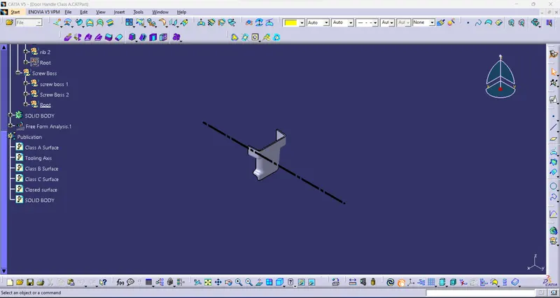
Tooling Axis:
- Tooling Axis is a line in which the core & cavity is open.
- create an intersection on both sides to check the center of the axis
- To create a point using the surface to generate the line to the center of the tooling axis.
- To change the name to Tooling axis.
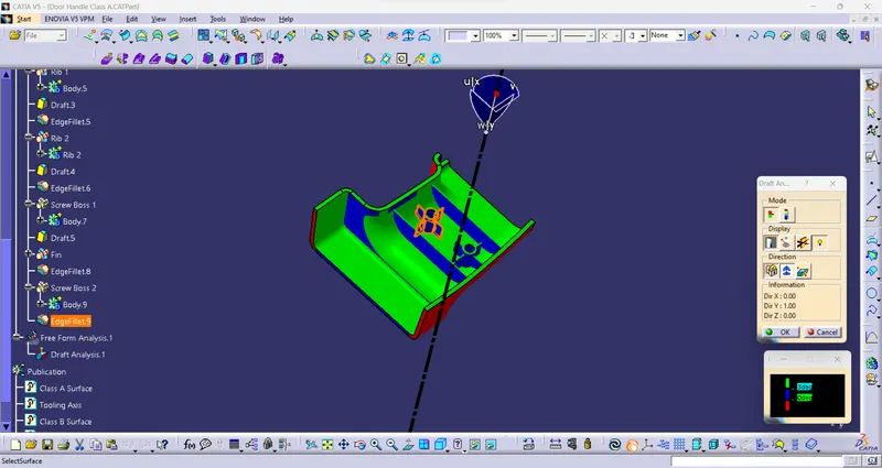
Draft analysis:
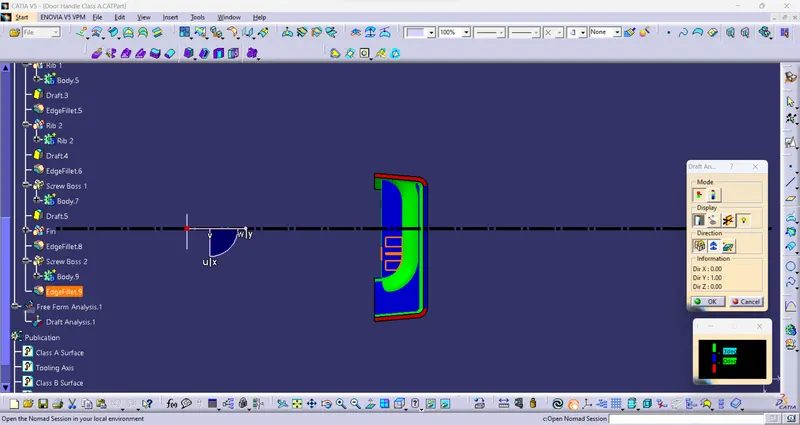
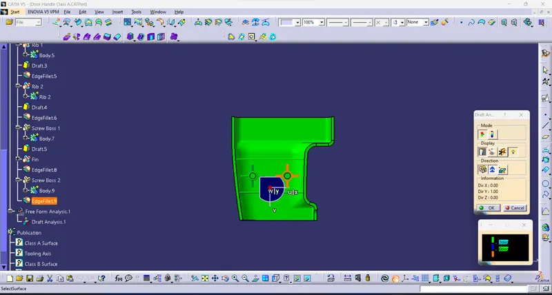
- Analysis of the draft angle of the completed solid model.
- Using this command to check the possibility of the draft angle for tooling direction.
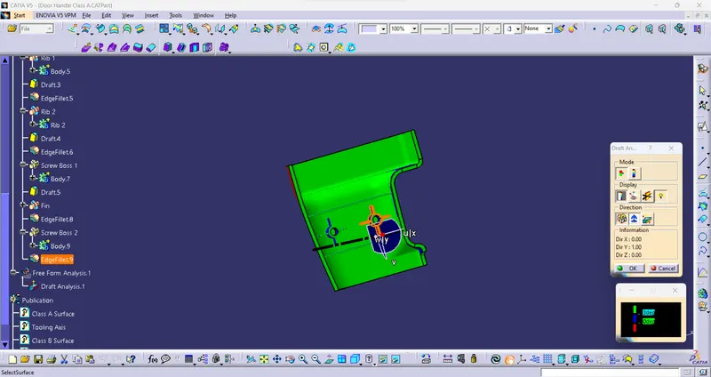
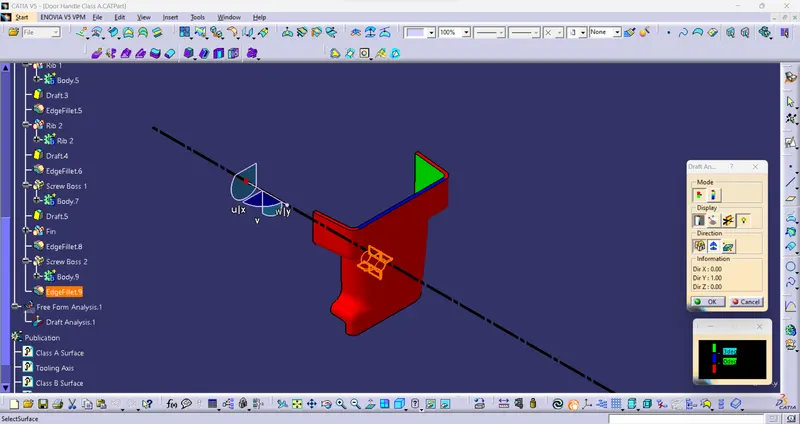
- The green color in the correct body or possible side.
- Blue is between the 0 to 3° angle.
- Red is a negative angle not possible.
- This draft analysis uses the tooling direction to analyze all the angles of the solid surface.
View:
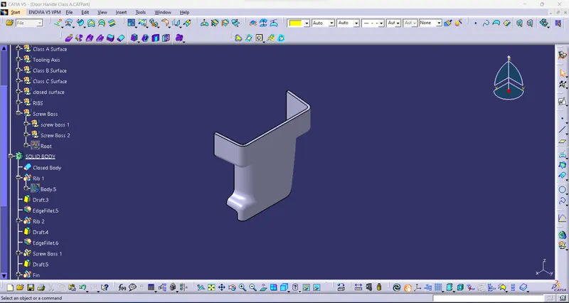
Isometric View:
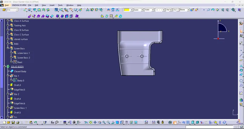
Front view:
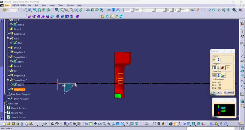
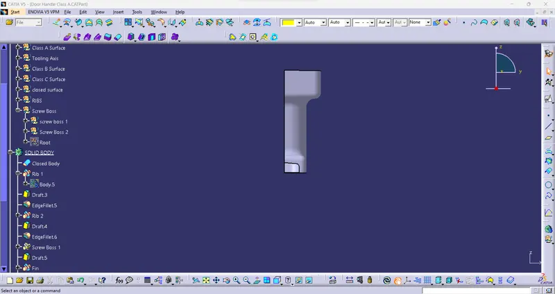
Side View:
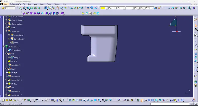
Top View:
DOOR HANDLE
Surface modeling :
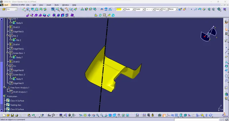
Class A surface:
- class a is an input to get stylish.
- check the class A surface to fully closed surface or not.
- the use to create class B surface.
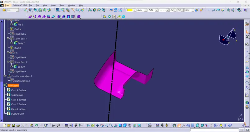
Class B surface:
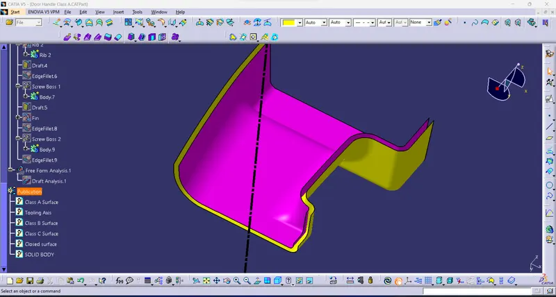
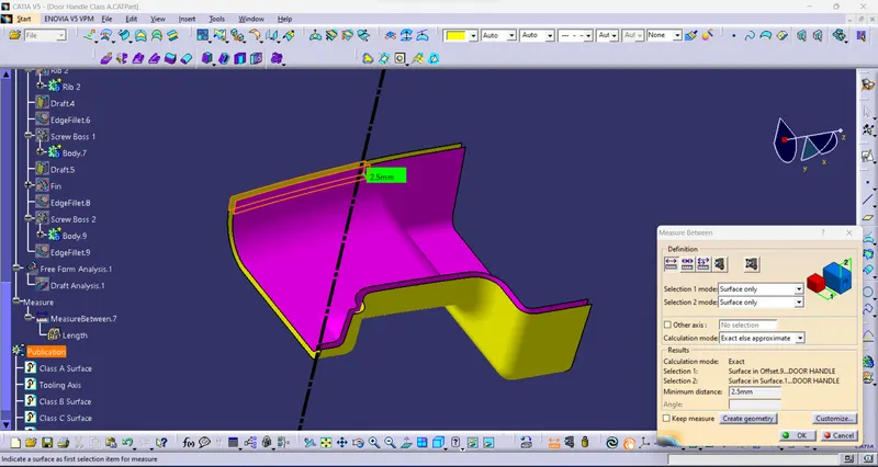
- Class B surface has Extracted the surface from the class A surface.
- First, offset the surface for a 2.5mm thickness.
- Finally, create a class B surface:
Class C Surface:
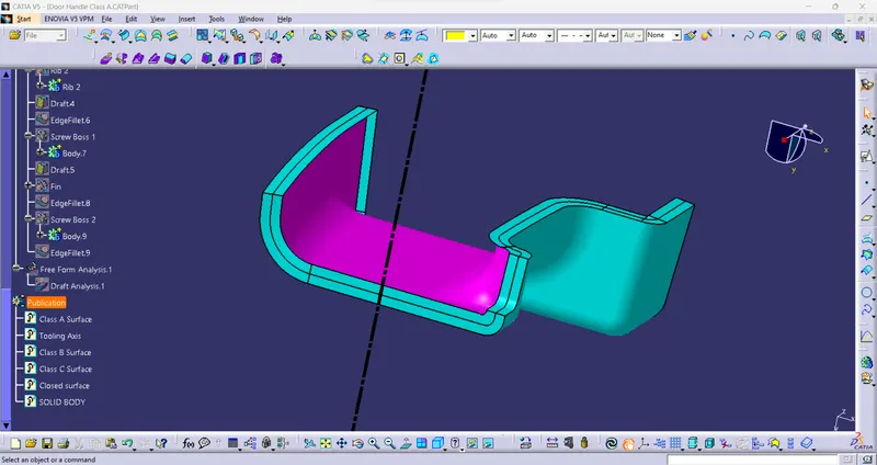
- create class C surface used to Sweep command to close the surface then trim the body.
- to close the surface.
- To get the closed surface
Closed Surface:
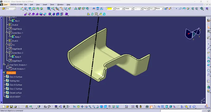
- Trim both class c and class B surfaces to get the closed surface.
Closed body:
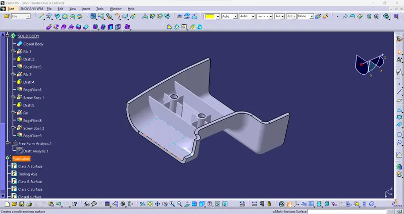
Rib and Screw boss design:
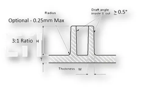
Rib:
- Increase the stiffness of the component without increasing the wall thickness.
- It is an economical way to increase stiffness.
- Locating and arresting components of an assembly.
- Providing alignment in mating parts.
- Acting as stops or guides for mechanisms.
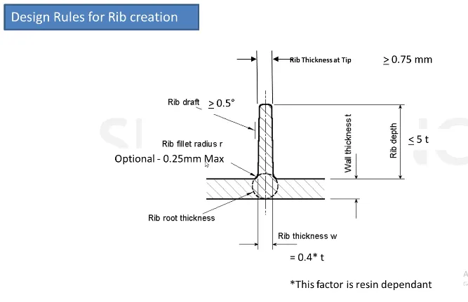
Guidelines of ribs on show surface:
- Draft.
- Thickness
- Height.
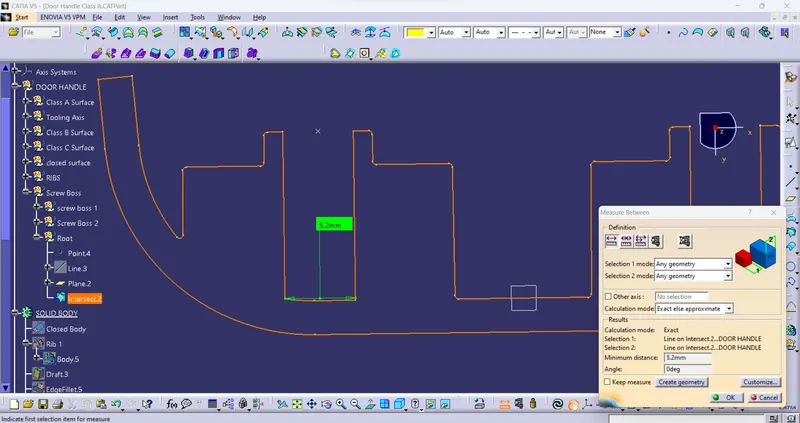
- Spacing:
- Thickness at the top.
- Optimal radius.
- Design suggestions.
Draft:
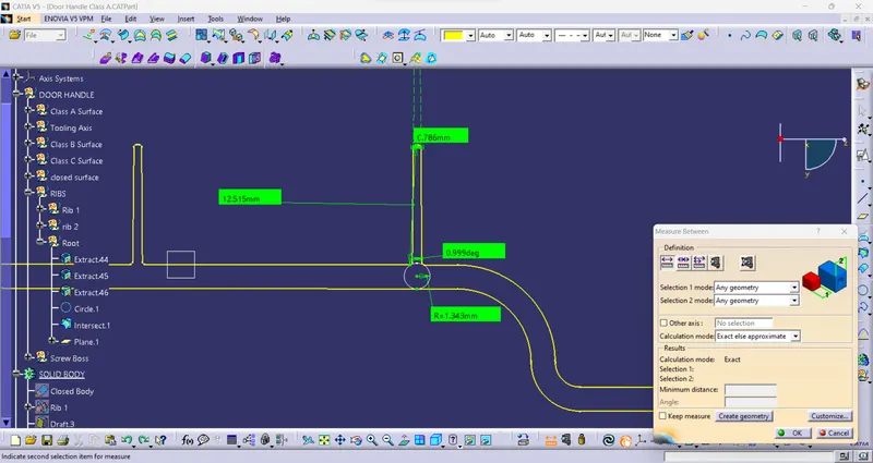
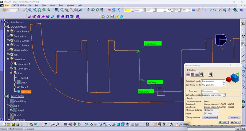
- Min. 0.5° per side.
- allows the rib released from the mold.
Wall Thickness:
W=0.4Xt
- measure the base thickness of the rib at the tangent of radius if radial is modeled in.
- The larger the area at the base of the rib the more retained heat.
- the retained heat causes more shrinkage which causes sinking.
Rib thickness of Top
- minimum thickness at rib tip 0.75.
Rib fillet radius :
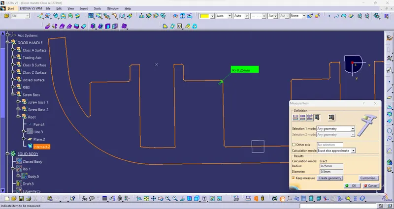
- Optional rib fillet radius - 0.25mm maximum.
- do not want significantly increases rib thickness
- must not violate 40% thickness requirement.
Rib height:
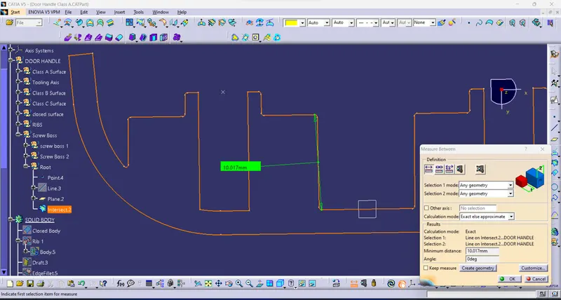
- Rib height <5X nominal wall thickness
- Limited by draft and thickness requirements.
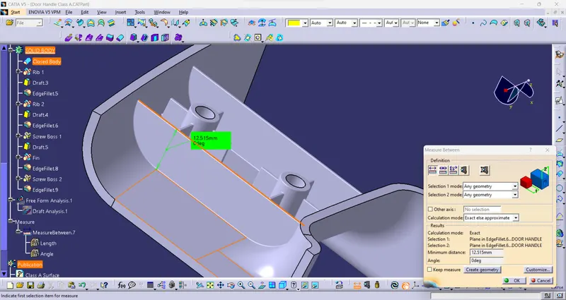
Spacing:
- Height/width ratio.
- 3:1 steel
- 2:1 is preferred.
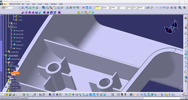
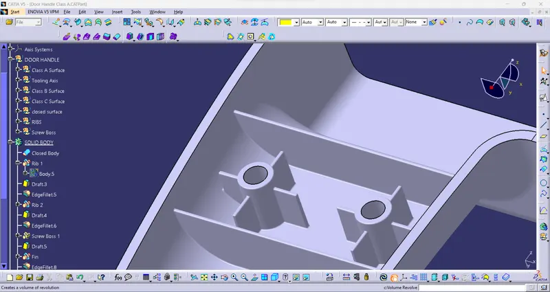
Screw Boss:
- Bosses find use in many part designs as points for attachment and assembly.
- the most variety consists of cylindrical with holes designed to receive screws, threaded with holes designed to receive screws, threaded inserts, or other types of fastening hardware.
General guidelines of Screw boss:
- draft 0.5° on the wall of the screw boss.
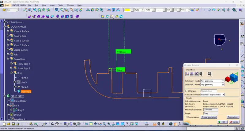
- Thickness - Typically 40% of the nominal wall at the base.
- Height to diameter ratio 3:1.
- Radil 0.25mm maximum radii.
- boss gussets must meet rib guidelines
- Need to plan ahead for the type of ejection
Finished Body:
Isometric view:
Front View:
Side View:
Top View:
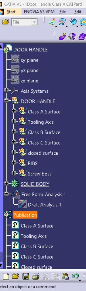
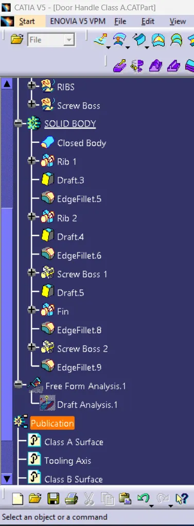
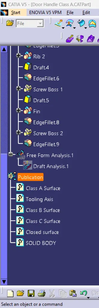
Tree Management: