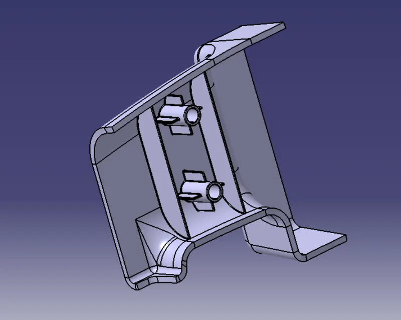
Week 9 - Attachment Feature Creation (Ribs & Screw Boss) - Challenge 1
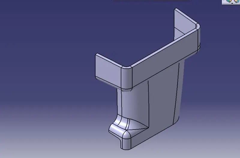
We have received a Door handle as class A surface.We check the connectivity of our class A surface using boundary command.
Since their is no gap, we start our 1st step.
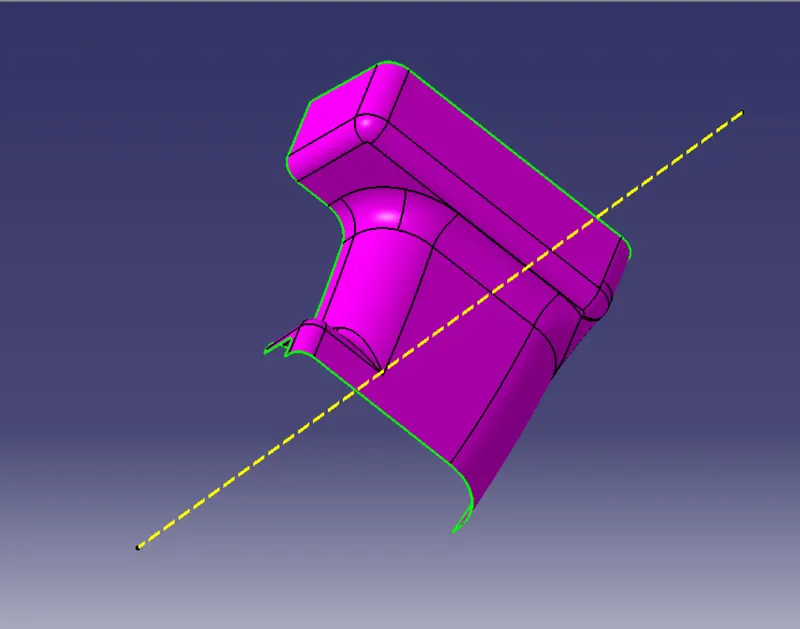
Step-1 Selection Of Tooling Axis
Tooling Axis-The direction in which core and cavity open is tooling axis.
- So after visualising we can say that Y-direction is tooling Axis direction.
- We selected lower flat face of the Class A surface and extract it.
- MAke a point on extract surface.
- Make a line passing through point and normal to surface.
- This is our tooling axis.
Step- 2 Draft analysis for CLASS A -Surface
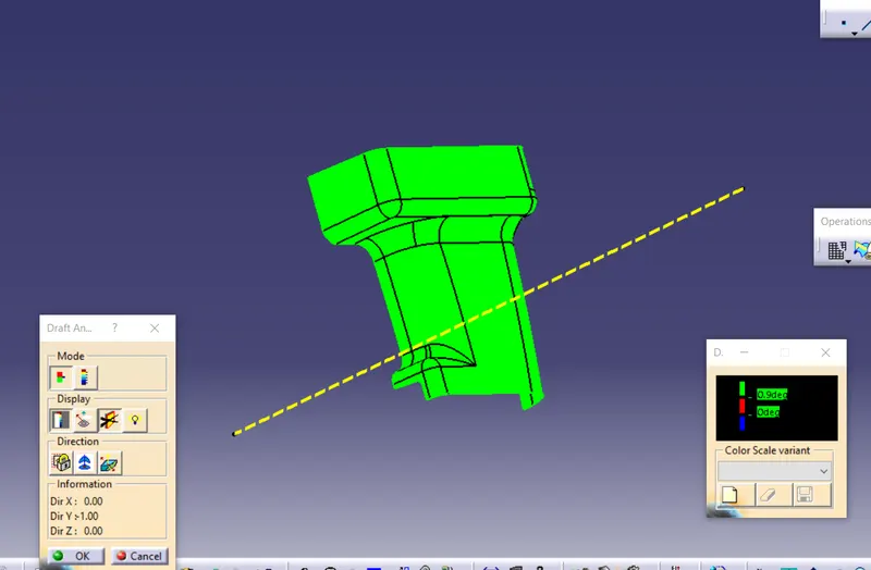
- Insert > Analysis > Features draft analysis
- Make sure view mode Customization to Material mode
- Now go to direction, and click 2nd option.
- Pick the compass and align it with the tooling Axis and click on the lock .
- Now click on the class A surface,here we notice there are some part when our draft angle is 3 degree.
- This is happening becausing some face of class A is not given proper draft angle.
- If we provide 0.9 degree, Class-A will clear.
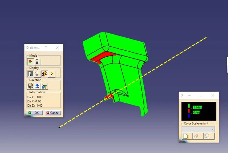
As we notice here when we are giving 2.9 draft angles, there are so,e red faces. which have .9 degree draft.
Step-3 Class-B Surface
- Offset the class A , 2.5mm.
- Now we have to fill the patch using Multi-section surface.
- So extract boundary and use MSS , join the offset with it.
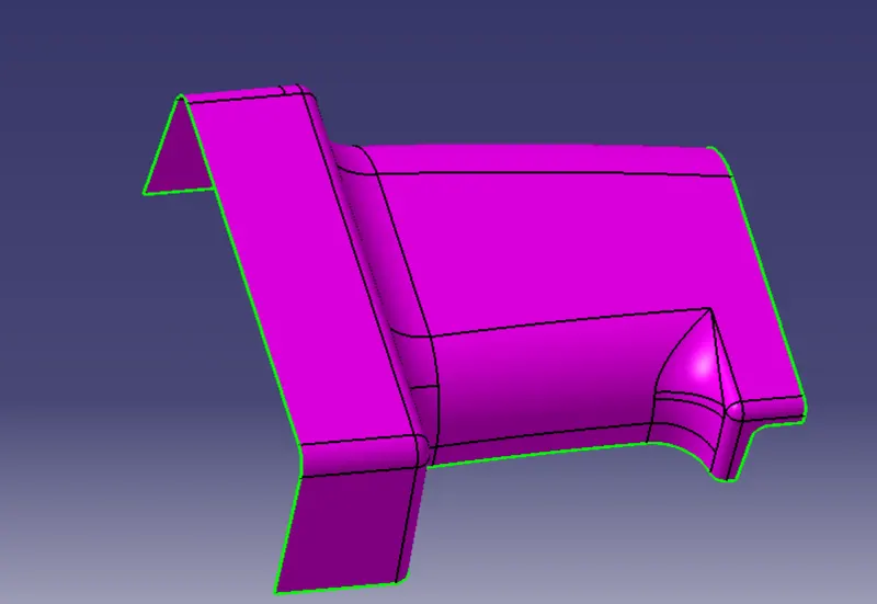
B-SURFACE
CREATING C-SURFACE
- We will used boundary command and extraxt outside of one side
- Sweep using draft durection(as shown below image)
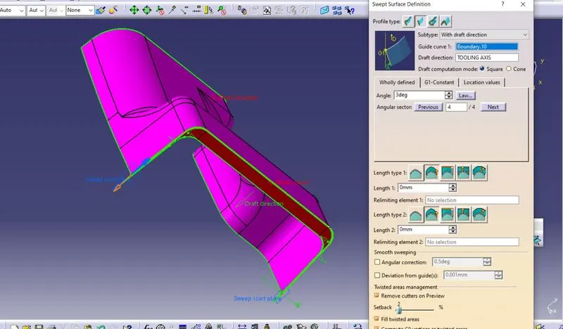
- As we see some part of C- surface are not proper.
- So we will extract the needed part, this will be 1st part of C surface.
- We also repeated same process in opposite side.
- Now use sweep using reference surface in other side (as shown in below image)
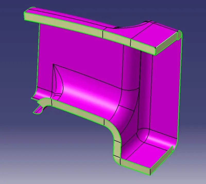
- Now use multi selection surface in remaining area.
- Since some corner C-surface were not touching, so i have extrapolate them and trim them.
- now join them together
C-SURFACE
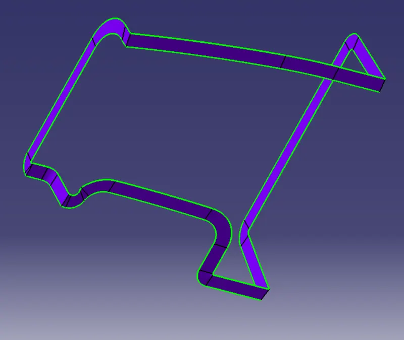
- Now join C with A Surface
- Trim the above join with B - surface.
A+B+C surface
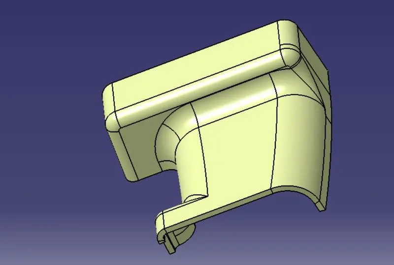
Step-5 Draft analysis report for the final plastic component
Draft analysis tell whether our component is manufacturable or not, if it's green it clears but if it's red means the surface is not clearing.
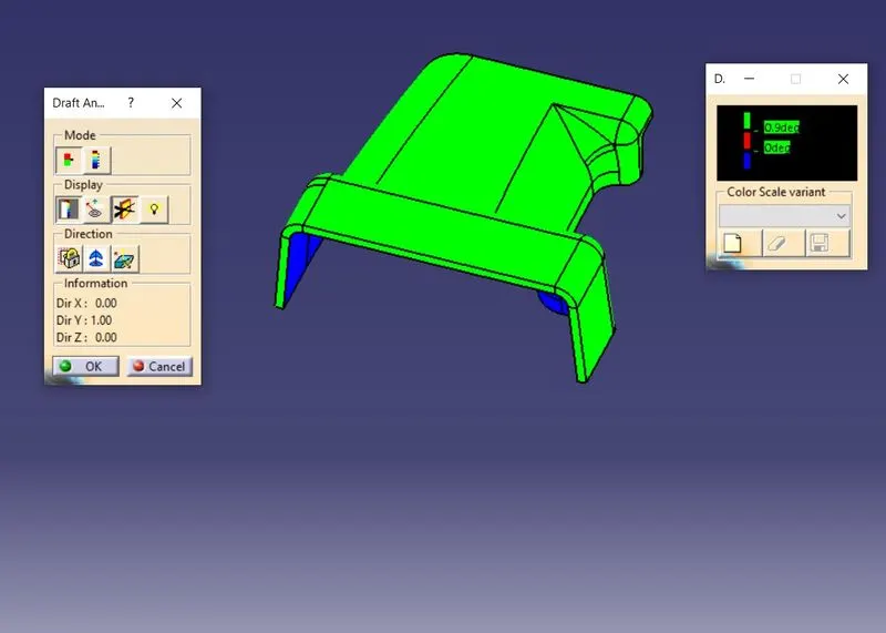
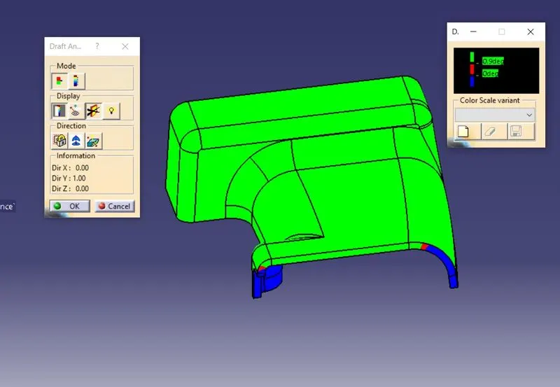
As we can see in above image their is small red portion, because we can notice ,in that area our angle is changing from +ive to -ive. I tried to clear it by using other methods but it was not clear, so at last i have used multi-section surface.
STEP-6 CREATING RIBS
RIBS- Rib is B side engineerning feature which is basic used provide strength to components. wiyh increasing overall thickness.
DIMENSION FOR RIBS
DRAFT=5 DEGREE
THICKNESS OF RIB= 1mm
Height = 12mm
Thickness at Top= 0.795mm
Root Diameter= 2.686
Fillets=0.25mm
Space = We generally take 2*t or more but we have taken more.
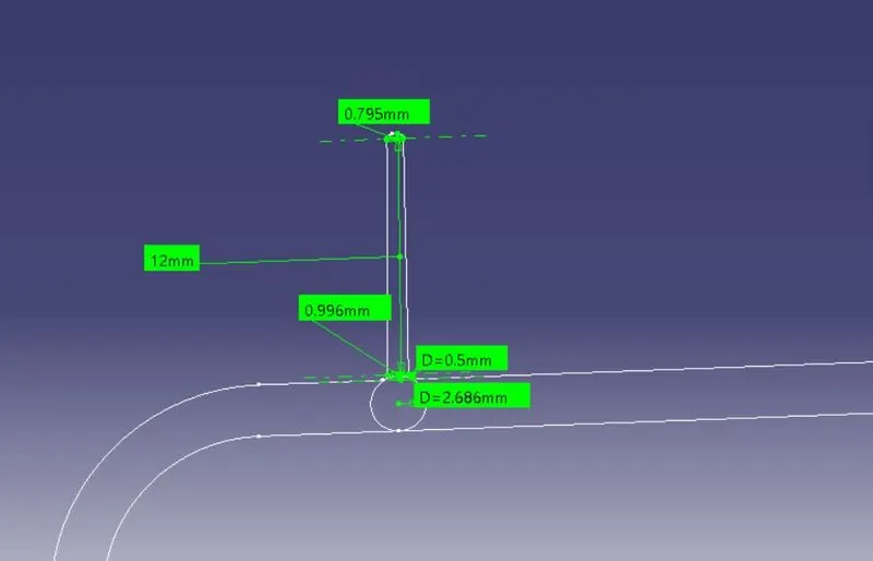
- Make a plane on B-surface
- Now i drawn a sketch, which is a straight line.
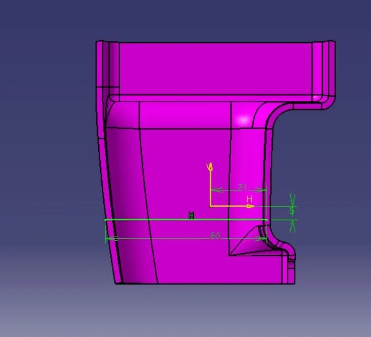
- now extrude this line, take the direction as Tooling Axis
- distance of extrude is = 12 mm
- Now provide thickness using Thick Surface.
- Both side =0.5mm
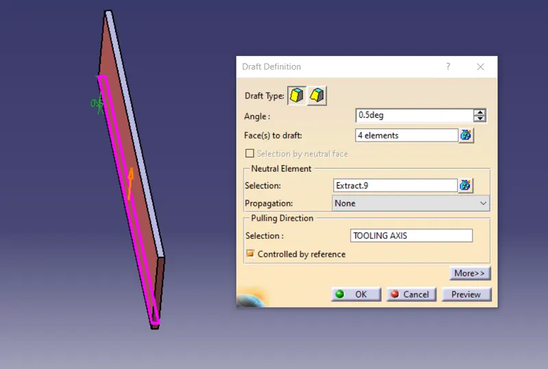
- Now provide draft =0.5 degree, pulling dirction as Tooling Axis.
Image of Rib and Draft
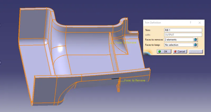
- use the Union Trim with main body, select face to remove and remove unwanted part.
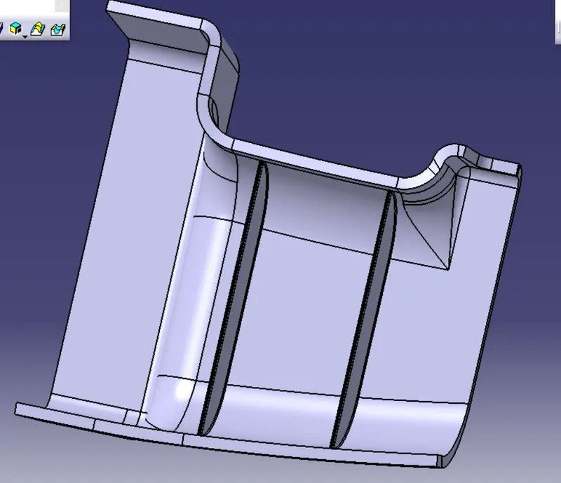
- Provide the fillet and our 1st RIB is ready
- Reapeat same steps for 2nd rib and provide fillets
IMAGE OF RIBS
STEP-7 CREATING SCREW BOSS
SCREW BOSS- It is featurewhich hwlp to screw/attach two component together.
DIMENSION-
DRAFT=5 DEGREE
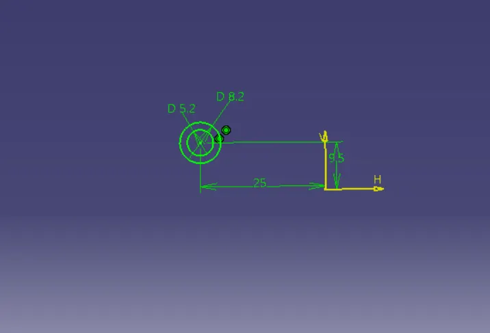
DIAMETER OF HOLE = 5.2mm
THICKNESS OF WALL= 1mm
Height = 15.6mm
OUTER DIAMETER=8.2mm
Fillets=0.25mm
- Make a sketch for make diameter of screw boss, as shown in below figure
- create a Pad, h=15.6mm
- Provide the draft 0.5 degree outside
- Also provide the draft inside.
- Now we will support rib structure.
- make a sketch as shown in below image
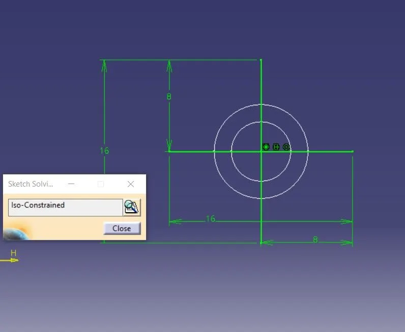
- now create a pad for this sketch and make sure the thick option is on.
- this is our rib ,so we have to fellow all design rules for RIB, like proper thickness, height, and draft.
- Now union trim screw hole with supportive rib.
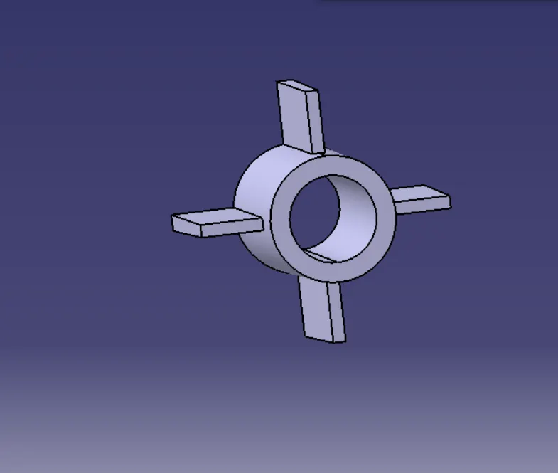
- unoin trim screw boss with main body and provide fillets
- Now use translation for making other screw boss.
- Again trim screw boss with main body and remove unwanted faces and provide fillets
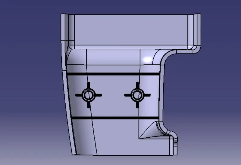
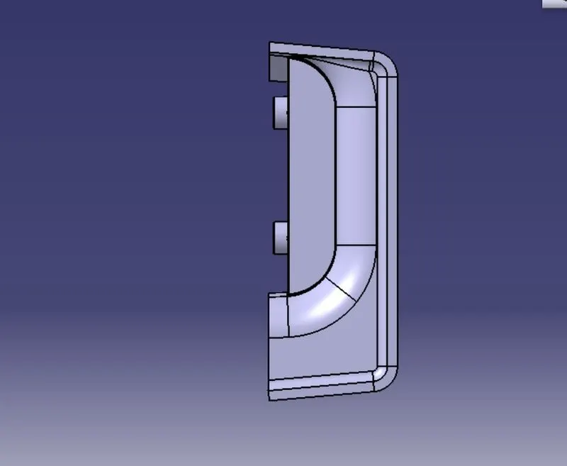
- Our output is Ready
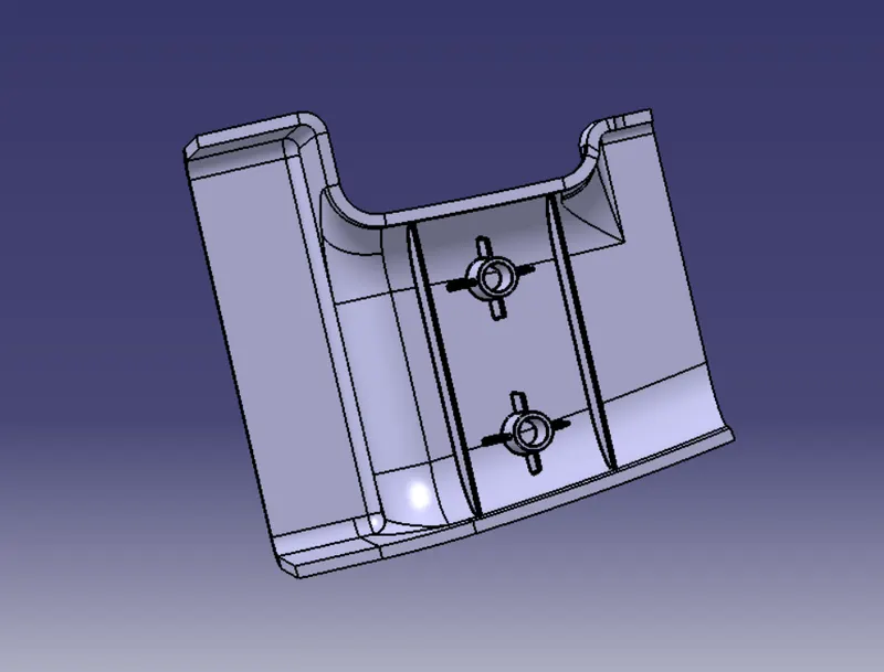
Step-5 Draft analysis report for Screw Boss and RIBS
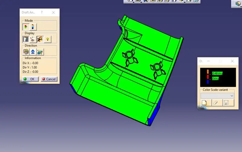
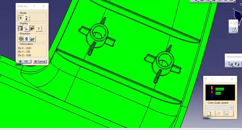
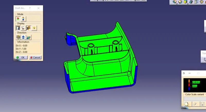
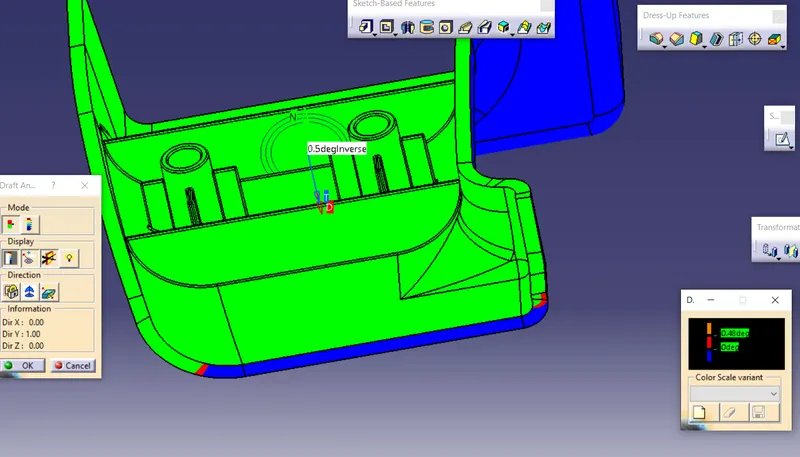
NOTE- I have taken 0.48 degree at draft analysis,because when i was taking 0.49 it was not clearing and also i measure the angle at ribs and screw boss the value is 0.5 degree everywhere.
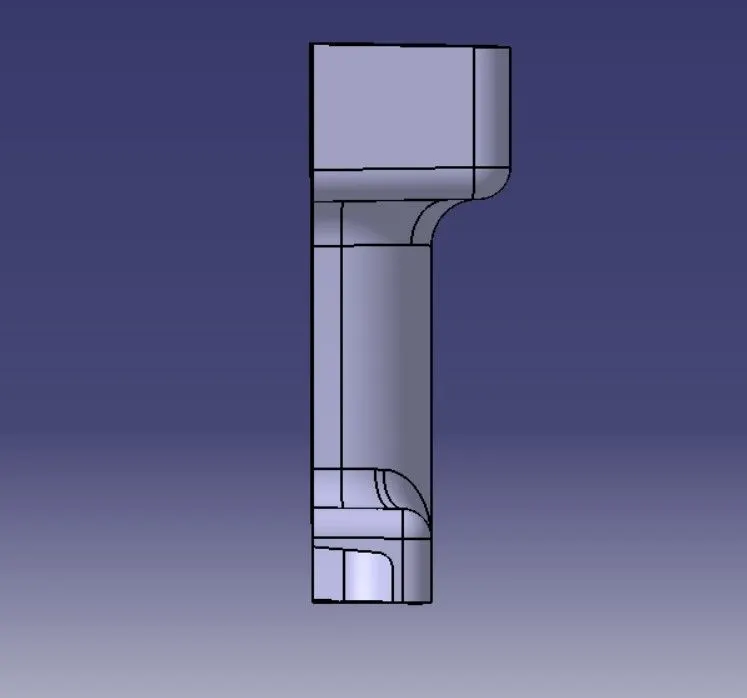
VIEWS