Week 9 - Attachment Feature Creation (Ribs & Screw Boss) - Challenge 1
Design Procedure
- First, check whether the given A surface is perfect and has a continuous boundary.
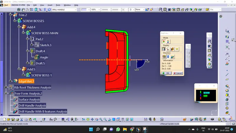
- Create a TOOLING AXIS and perform a Draft Analysis to check whether it is clearing or not.
- Then create a B surface and C surface and connect these surfaces with the given A surface to form a Part body.
- Perform a Draft Analysis with the Draft angle of 2.9 degrees and check whether it is clearing or not.
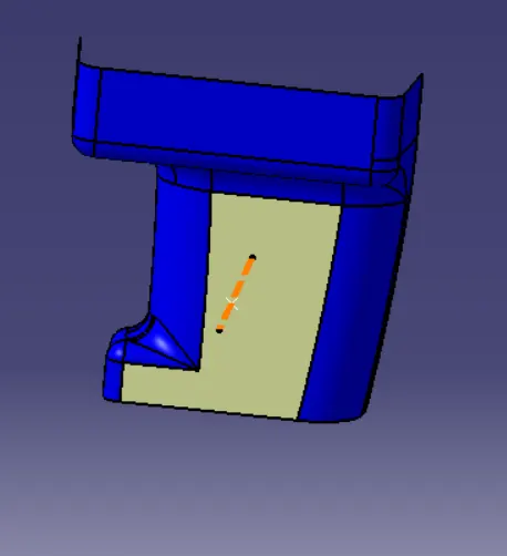
- Now create the B-side features like RIBS and SCREW BOSSES considering the design rules.
- Again perform a Draft Analysis with an angle of 0.48 degrees and check whether it is clearing or not.
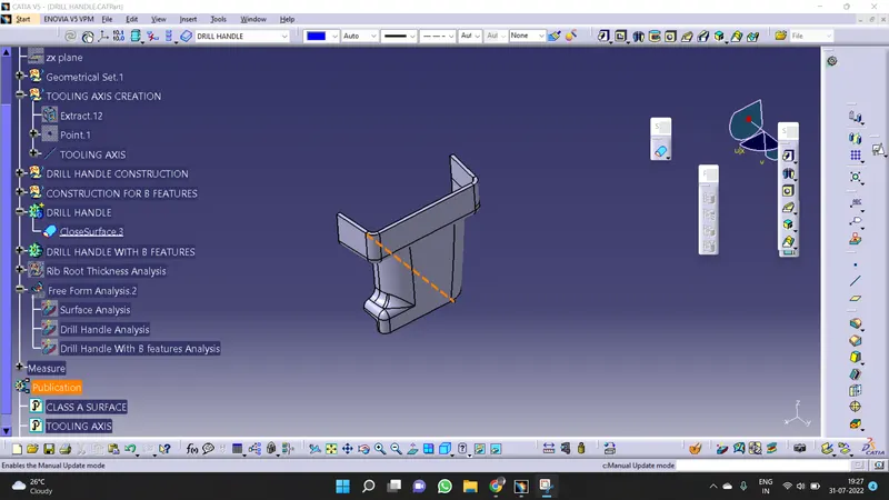
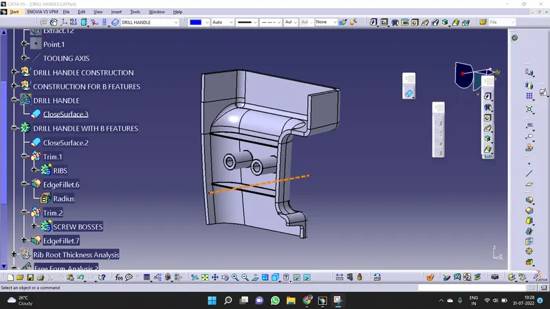
Draft Analysis On The Final Part
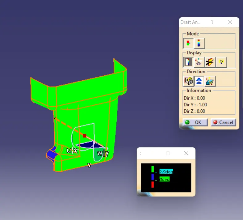
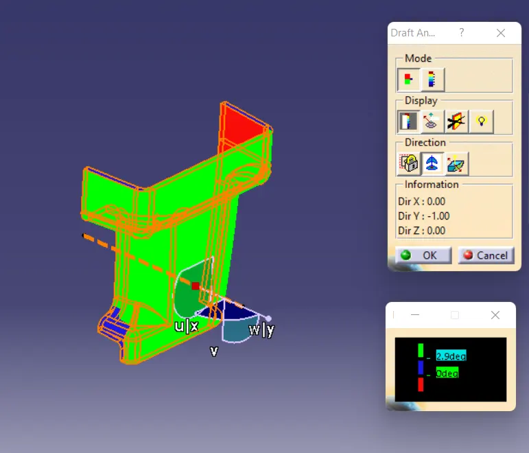
- Perform the Draft analysis on the Final part with B side Features.
- First, we need to drag the axis system and place it in a way that it is along the Tooling Axis.
- Change the Draft angle to 0.48 degrees and perform the analysis as the minimum draft angle provided to the Ribs and Screw bosses is 0.5 degrees.
- Then observe the color code to know the draft angle of the part on each and every surface of the part.
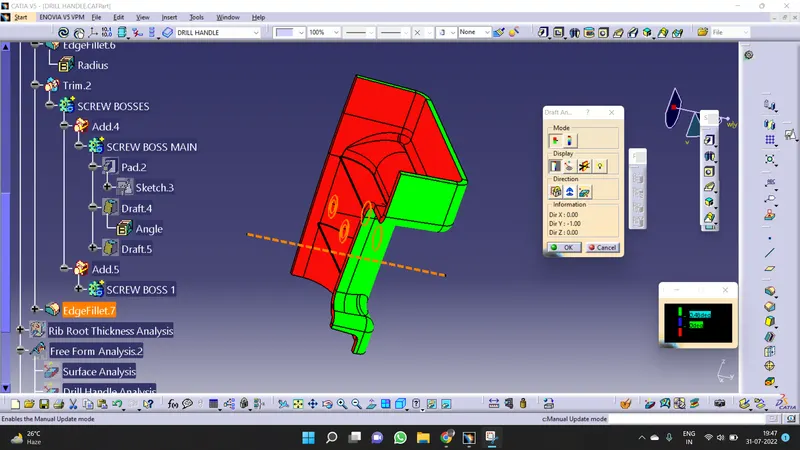
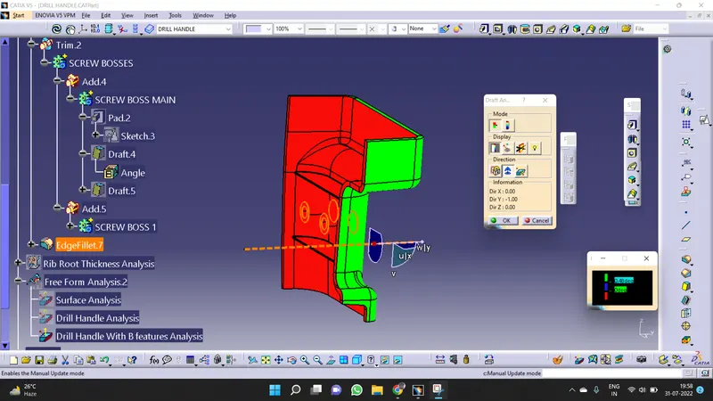
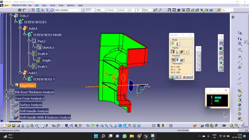
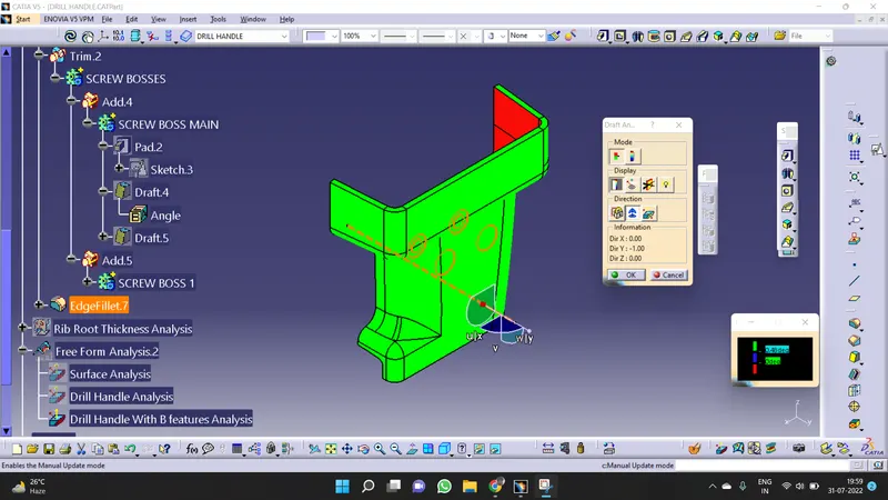
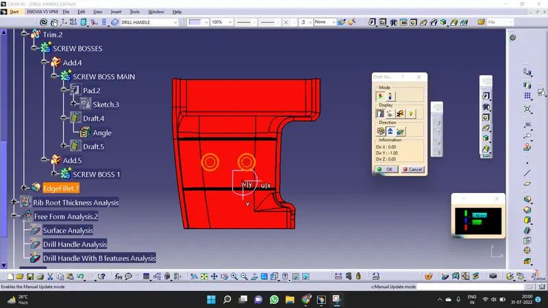
- As we observe the part after Draft Analysis we get a color code like the figure above.
- It depicts that the A surface of the part is clearing with the cavity side of the mold.
- B Surface and B side features of the part are clearing the Core of the mold.
- If we go by the color code we can see that the A side has a draft angle of more than .48 degrees when the axis is facing upwards.
- B surface and B side Features will have a Draft angle of fewer than .48 degrees when the axis is facing upwards.
- If we reverse the axis system we get Green on the B surface and Red on the A surface depicting the change in Draft Angles.