Week 9 - Attachment Feature Creation (Ribs & Screw Boss) - Challenge 1
AIM
- To create tooling axis for given class A surface.
- To create class B and class C surface.
- To create rib and screw boss design.
TOOLING AXIS CREATION
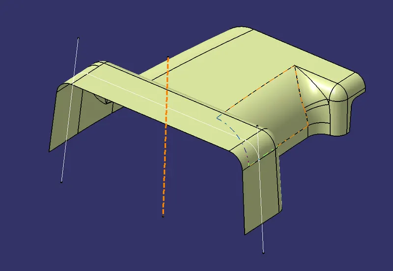
first we check the boundary condition on given class A surface.we have extrpolte the given class A surface on point on surface and then create axis on created point.now we have using intersect on given class A surface .next we have create the two lines on and then create the bisecting line method we have create the line on using point and axis that is called tooling axis.
B SURFACE CREATION
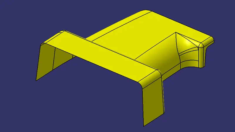
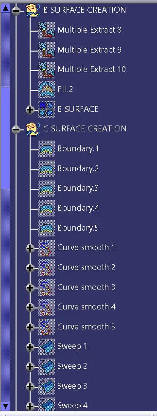
after creating tooling axis next we have create the b surface the offset of class A surface with require dimensions is called class B surface.in this case 2.5mm thickness during offset time missing
elements are created on class B surface.in this case we have one missing elements.so we have create boundary and then create fill command we get class B surface.
C SURFACE CREATION
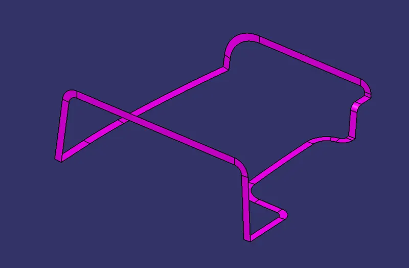
after creating b surface next we have create c surface.we have create boundary on given class A surface all the sides.to avoid patches using smooth curve option and then using sweep command on below
requirements.to joint the all the sweep we get the class c surface.
sub type:with reference surface
guide curve 1:boundary
reference surface:class A surface
angle:90 degree
length:3mm
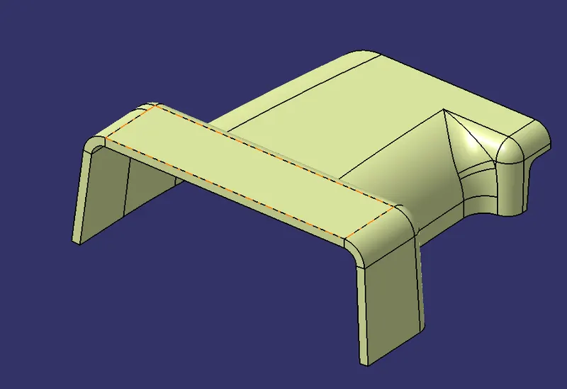
JOIN CLASS A & CLASS C SURFACE
CLOSED SURFACE
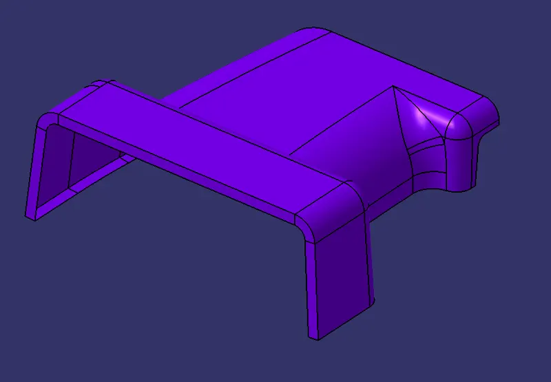
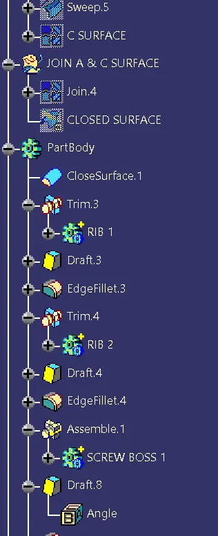
after join the class A and class C surface trim along with b surface we get closed surface.
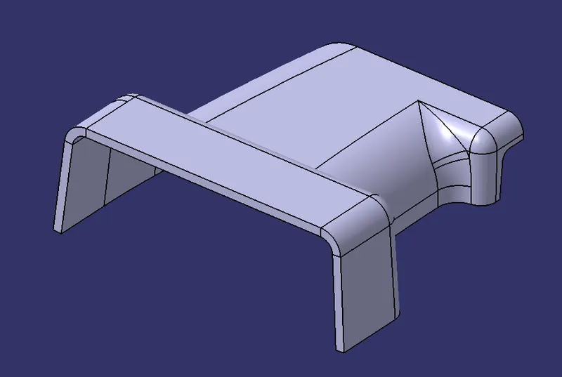
PART BODY
using part body closed surface option we get the solid body.
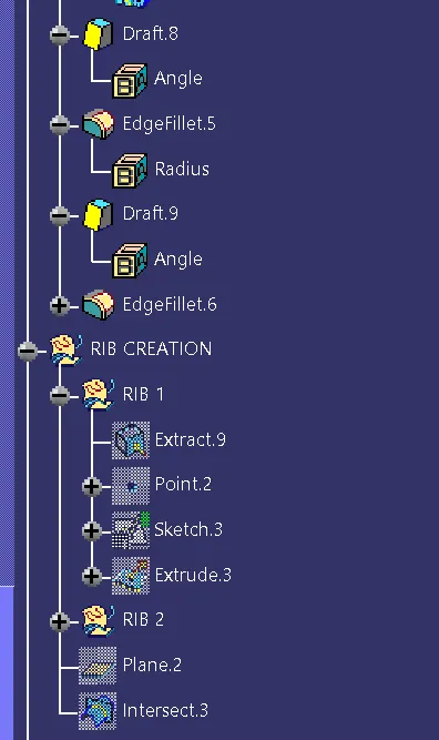
RIB CREATION
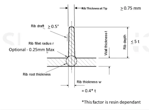
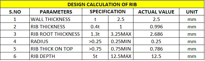
Ribs are used to strengthen the walls of your mould without increasing wall thickness which means that you minimise the problems that come into play when the wall thicknesses have to be increased. In essence, if the wall is too thick, warping and sinking can result so that the entire design may need to be rejected.
DESIGN RULES FOR RIB CREATION
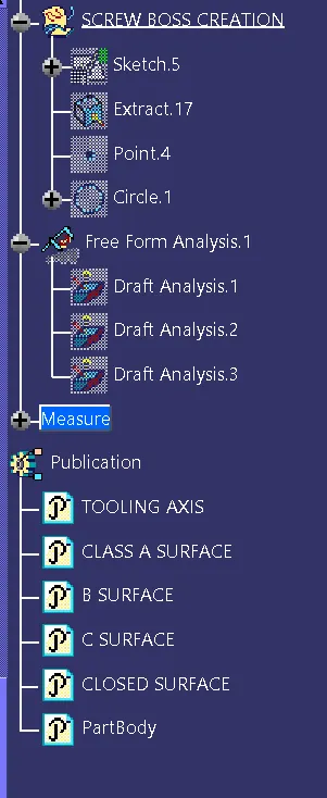
SCREW BOSS CREATION
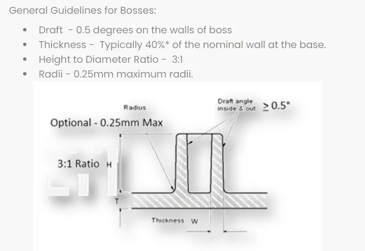
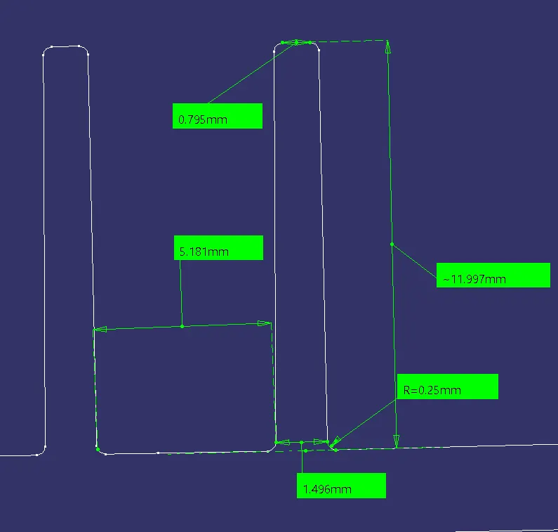
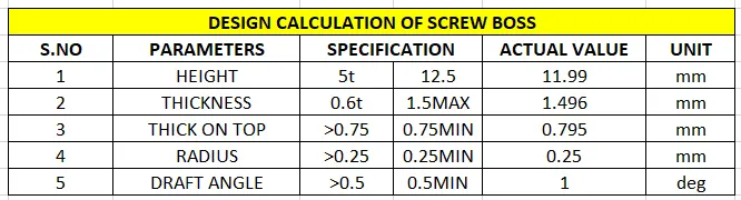
They are used to aid in the assembly of molded parts by providing a channel for a screw. Designing plastic screw bosses is fairly straightforward but there are a few considerations to ensure a strong connection between parts and mitigate cosmetic defects.
DESIGN RULES FOR SCREW BOSS
DRAFT ANALYSIS
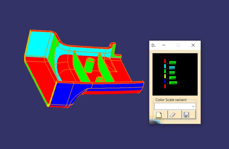
after creating rib and screw boss design we have analysis the class A and part body.use the compass to select the tooling direction.and then lock the direction.next we have analysis the running point.colour code
are classified after draft angle applied.running point analysis used to permissible draft angles.
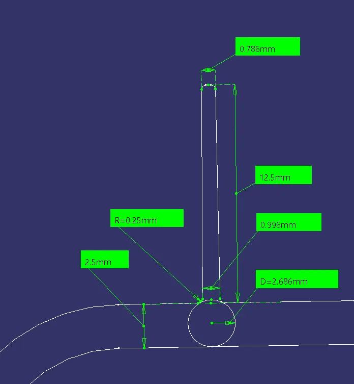
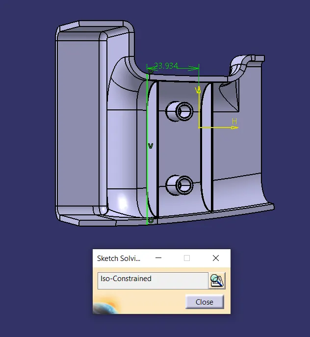
SKETCHING FOR RIB CREATION
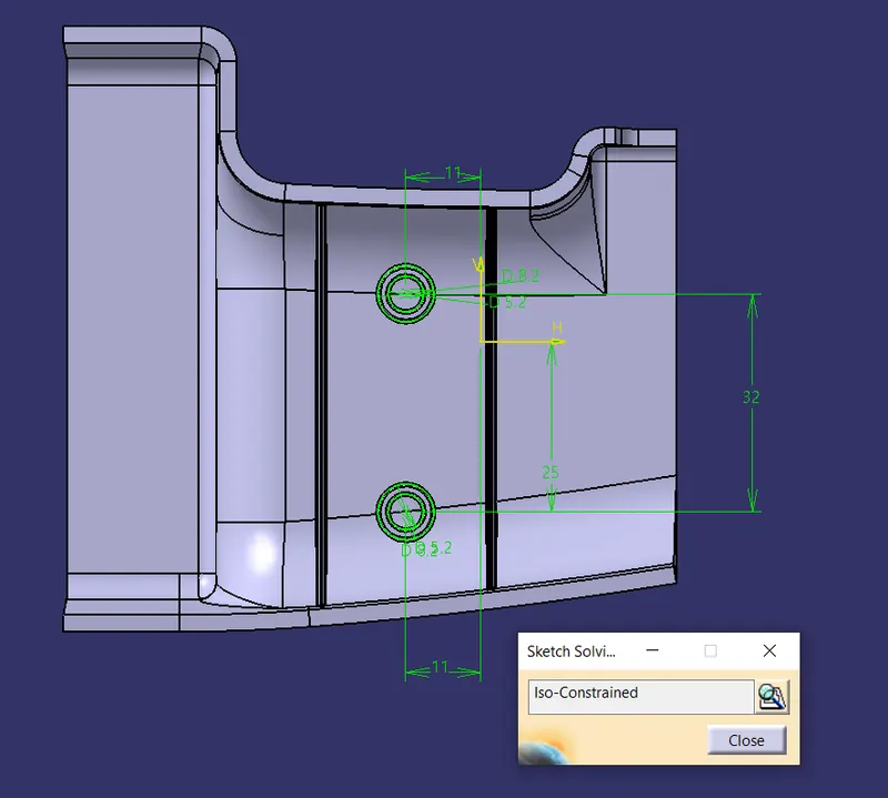
SKETCHING FOR SCREW BOSS CREATION
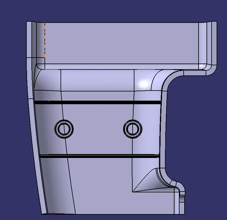
VIEWS
FRONT VIEW
BACK VIEW
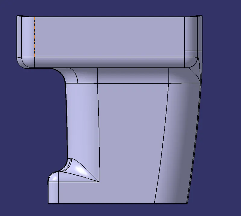
SIDE VIEW
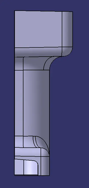
ISOMETRIC VIEW
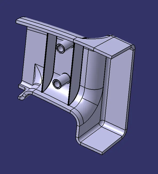
TREE STRUCTURE
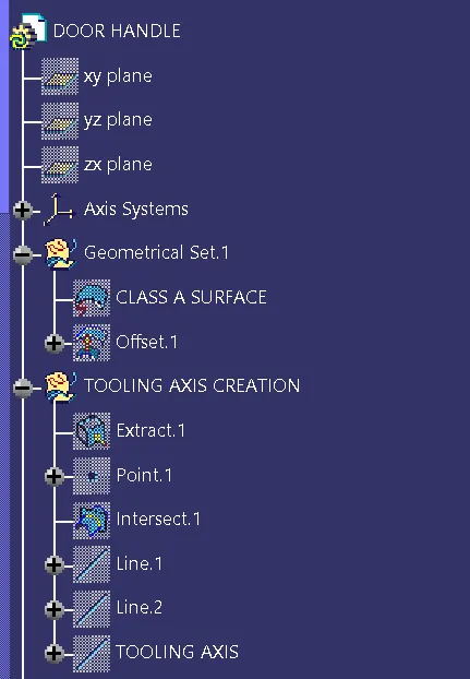
CONCLUSION
successfully we have created rib and screw boss design as per design rules for door handle part body.