Week 9 - Attachment Feature Creation (Ribs & Screw Boss) - Challenge 1
RIBS & SCREW BOSS DESIGN:
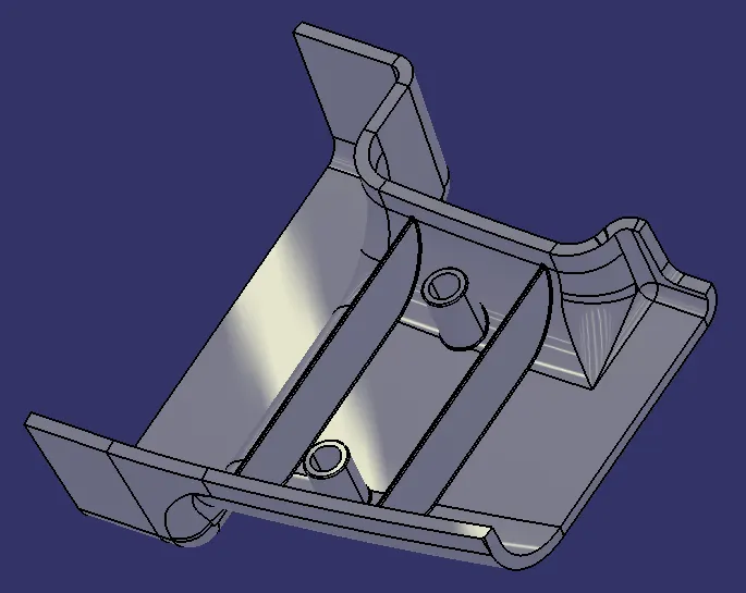
AIM: To create the Drill Handle Plastic component through the given Class-A surface by creating a tooling axis meeting the requirements of the draft angle, Create the Ribs and Screw boss for the Drill Handle considering the design rules mentioned in the video and to perform the Draft Analysis on the solid model at the end.
GIVEN CLASS A SURFACE:
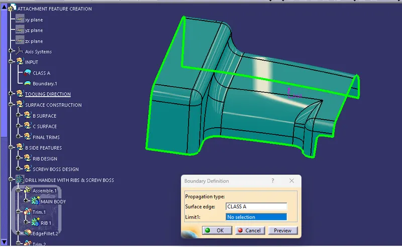
The Class A surface is given to us as an input which is quality checked for any open profiles inside the geometry using the "Boundary" command before starting the construction of Class B and C surfaces.
REPORT ON DRAFT ANALYSIS AND TOOLING AXIS CREATION:
DRAFT: It is the degree of taper that is incorporated into the side wall and cores of the die cast tool to aid in the removal of a part. Primarily, they function to reduce the friction between the part and the tool as it is ejected. Without draft angles, parts can be stripped, dented, or get stuck in the tool.
The Draft Analysis command enables you to detect if the part you drafted will be easily removed. In the case of plastic injection molded parts it also allows the designer to see if there is enough draft on the part to ensure that it can be correctly grained.
TOOLING AXIS CREATION:
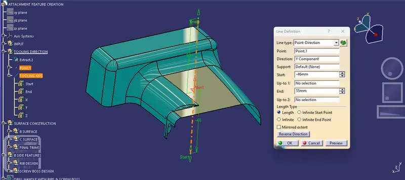
Tooling axis is the direction that the mold pulls apart. It is necessary to create a tooling axis to give draft to the component. Tooling axis is created using the Bisecting Method or Hit and Trail to acquire the required draft. For the given Class A surface, the best tooling direction for the component is chosen by considering the tooling of the final product. It is chosen in such a way that the component is cleared with minimum tooling.
BISECTING METHOD:
In Bisecting Method, an axis is created by bisecting the lines that lie on the opposite walls or faces of the surface which can be done by using intersection of the of the Class A with the plane of intersection. The walls or faces that may probably create a problem during tooling are selected for intersection with the plane.
For this Class A surface, an axis is created in the direction of Y-axis as the component clears tooling in this direction which can be observed by looking at the Class A in various dcirections as the maximum faces of the surface are visible in this direction.
CLASS A DRAFT ANALYSIS:
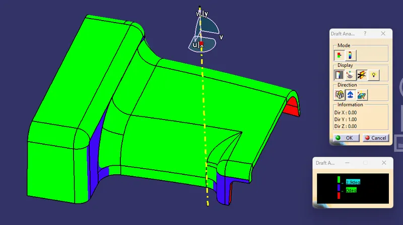
Draft Analysis is performed on the Class A Surface using the Draft Analysis command in CATIA after creating the Tooling axis. It is performed to check if the surface clears the tooling. The compass is used to define the current draft direction. It is aligned with the Tooling Axis to define the draft direction and the surface is selected to perform the analysis.
NOTE: CLASS A SURFACE GIVEN TO US AS INPUT HAS THE WRONG DRAFT ANGLE AS CAN BE SEEN FROM THE BELOW PICTURE.
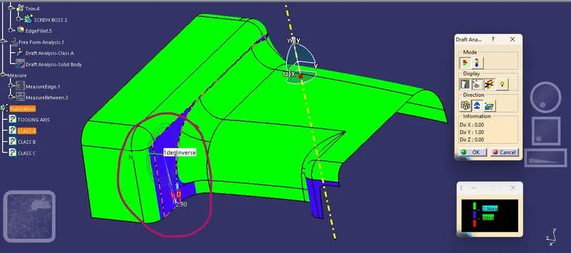
The Class A surface is not clearing the draft for tooling axis created in any method for 2.9 or 3 degree draft.
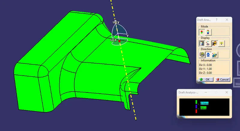
For an angle of 0.5 degree, it is clearing the draft as can be seen from the below picture.
DESIGN RULES FOR RIBS AND SCREW BOSS:
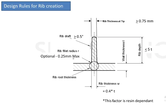
General Guidelines for Ribs:
- Draft - 0.5 degrees on the walls of ribs
- Rib Thickness - 0.4*Thickness of component
- Tip Thickness - ≥ 0.75 mm
- Depth - ≤ 5* Component Thickness
- Radii - 0.25mm maximum radii.
 |
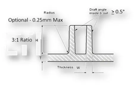
General Guidelines for Bosses:
- Draft - 0.5 degrees on the walls of boss
- Thickness - Typically 40%* of the nominal wall at the base.
- Height to Diameter Ratio - 3:1
- Radii - 0.25mm maximum radii.
 |
DRAFT ANALYSIS ON SOLID MODEL:
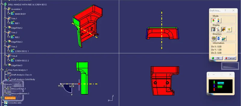
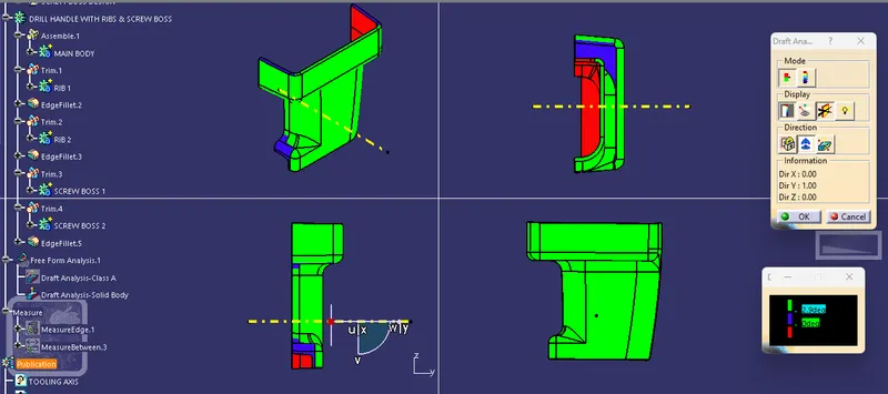
Draft Analysis is also done for the final Solid Model similar to the anlysis done for Class A surface to check if the body clears the tooling.
The results obtained for the Draft Analysis of solid body in quick and full analysis modes can be seen below:
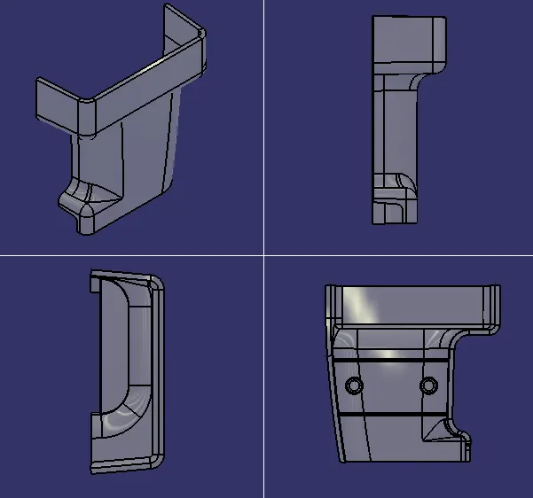
SOLID MODEL IN VARIOUS ORIENTATIONS:
After trimming and joining all the three Class A, B and C Surfaces, the final solid model is created in the part body using the Close Surface tool in the Part Design workbench. Then the attachment features - 'Ribs & Screw boss' are created on the the B Surface side by following their design guidelines. Finally they are joined with the main body to form a single part body.