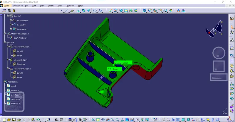
Week 9 - Attachment Feature Creation (Ribs & Screw Boss) - Challenge 1
1.First we get a A-surface which we join
2.Then we make the B-surface by off-seting A
do patch work on remaining surface which is not get off-set
3.then work on C-surface
4.Join A and C surface
5.trim with B-surface
6.Make the Final joined surface as a Closed solid in part workbench
now we have to start making sketch of the rib with Positioned sketch
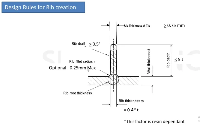
then consedering the designing rule consider the Rib hight (5 * Thickness of surface)
5 *3 = 15mm height
then the draft .5 per side
then the fillet angle .25mm Maximum
The upper edge should be 0.75m max
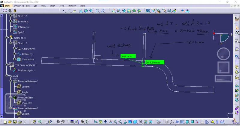
rib root thickness 40% of T
T=1.2
T=3+1.2=4.2 Max
Creating the rib for the Drill Handle considering the design rules mentioned in the video.
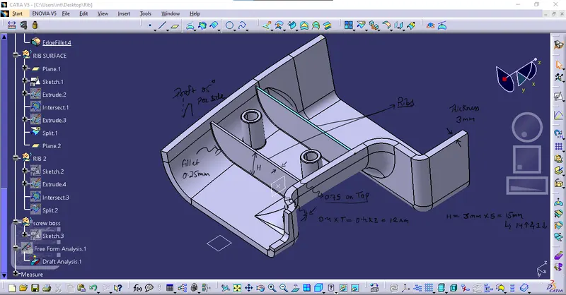
checking of rib (ribroot thickness)through Intersection
- Use Positioned sketch
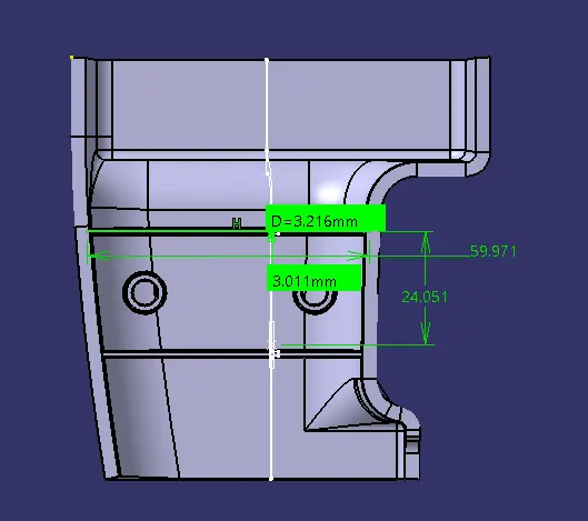
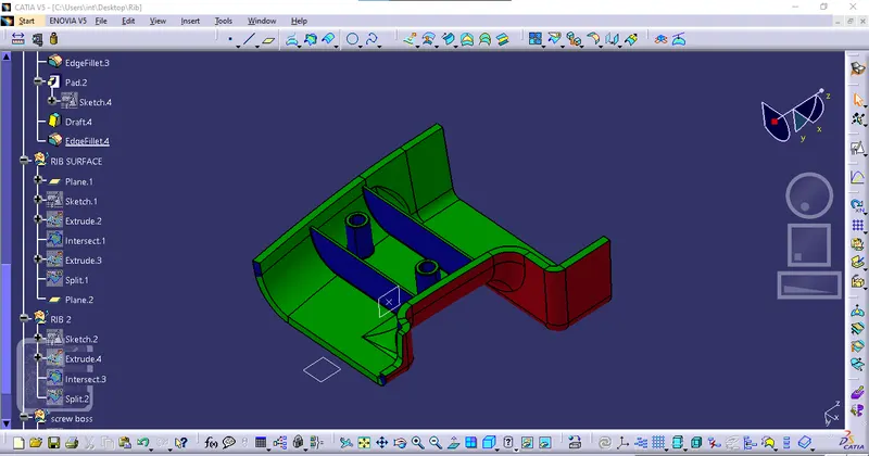
Create the 1. Screw boss for the Drill Handle considering the design rules mentioned in the video.
General Guidelines for Bosses:
- Draft - 0.5 degrees on the walls of boss
- Thickness - Typically 40%* of the nominal wall at the base.
- Height to Diameter Ratio - 3:1
- Radii - 0.25mm maximum radii.
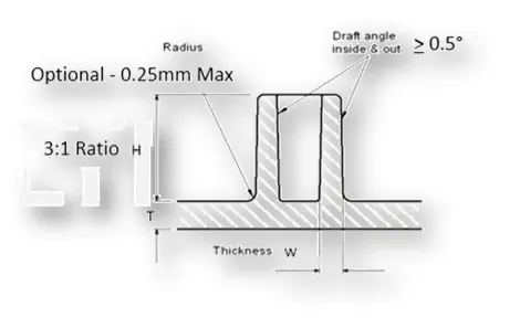
Now for the screw boss
First make the positioned sketch
Then the small circle of 5.2Dia
then the out side diameter will be 0.6 *T
0.6*3 =1.8 perside max
1.8*2 =3.6mm
therefor 5.2+3.6= 8.8mm Outer circle diamater
draft of .5 deg per side
filler on all face .25mm
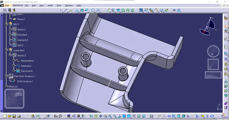
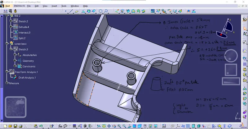
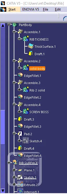
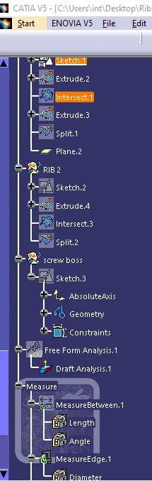
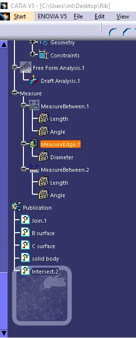
- Tree Structure
- Ensure Proper Tree Structure
- Geometrical sets should have a proper name based on the sketches present inside of it
- All the sketches should be created under the Geometrical set
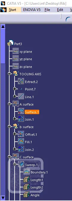
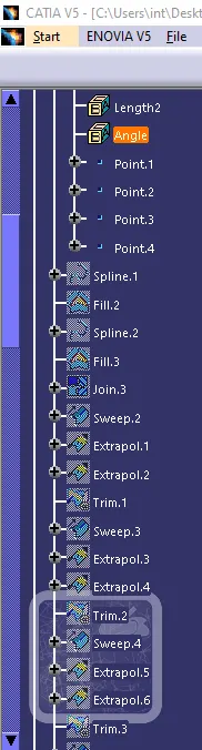
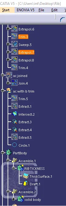
- Screenshots of the completed design in various orientations (Isometric, Front, Side, and Top View)
Isometric view
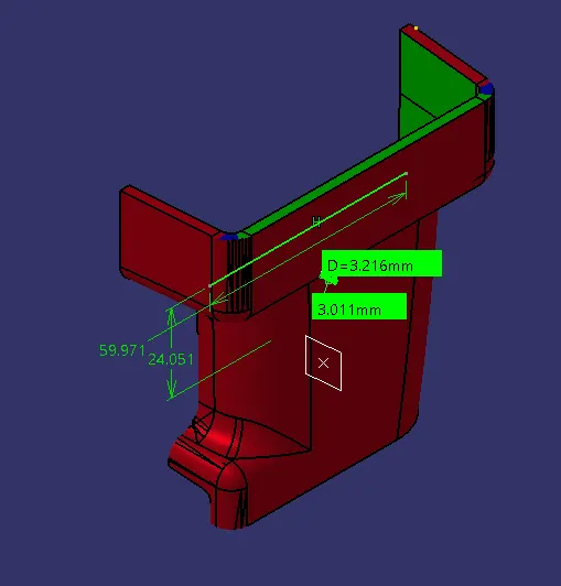
Front view
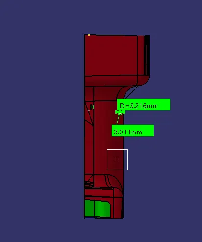
Backside view
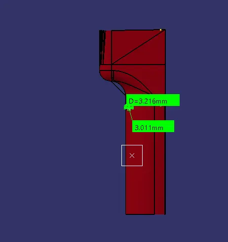
Leftside view
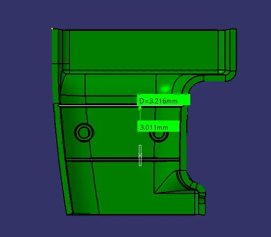
Right side view
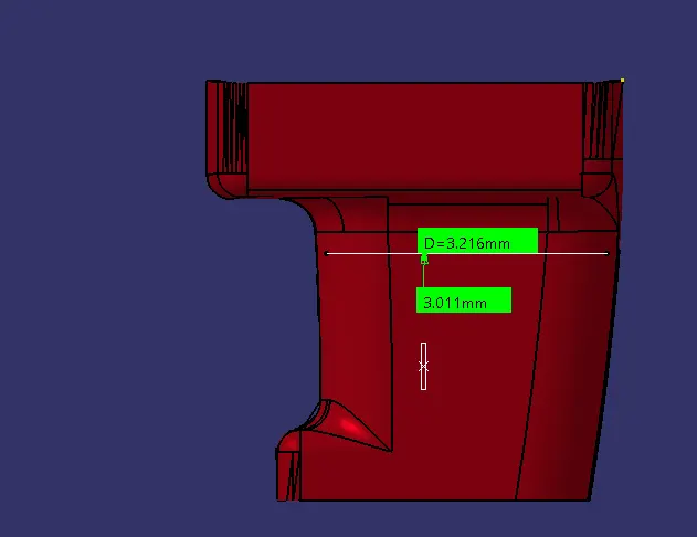
Top view
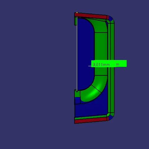
Final product