Week 9 - Attachment Feature Creation (Ribs & Screw Boss) - Challenge 1
CHALLENGE 27 – RIBS & SCREW BOSSES
Aim: Thicken the Drill Handle, add ribs and screw bosses according to the design rules and verify with draft analysis.
COMPLETED SWITCH BEZEL COMPONENT
We were provided a drill handle surface as below.
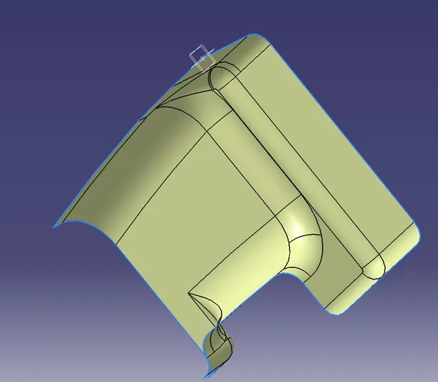
Fig 1a – Drill Handle Class A Surface
Rib Design Rule is as below:
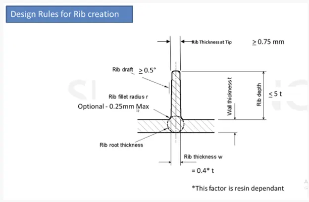
Fig 1b – Rib Design Rule
Screw Boss Design Rule is as below:
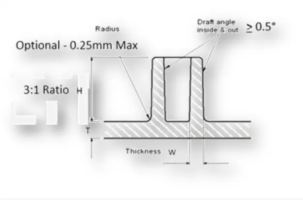
Fig 1c – Screw Boss Design Rule
We then created a Tooling Axis by bisecting two Sketch lines, as below.
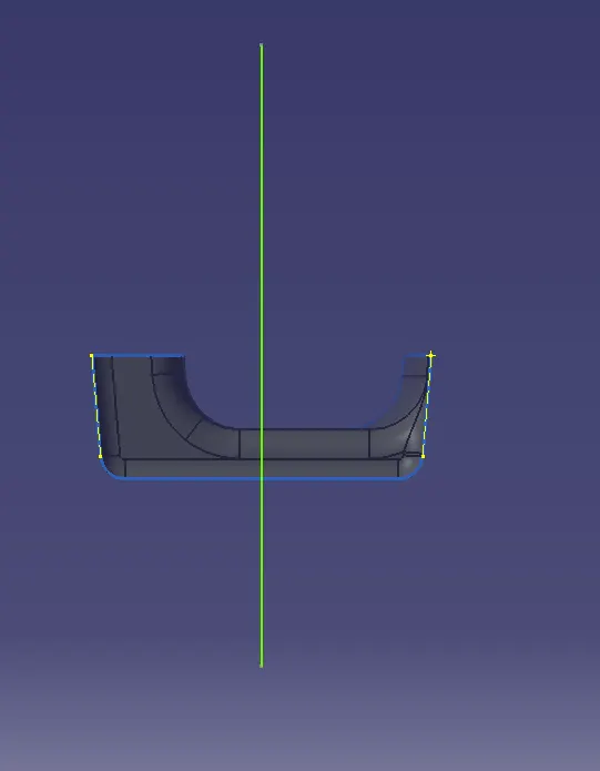
Fig 2a – PARTIAL TOOLING AXIS SKETCH
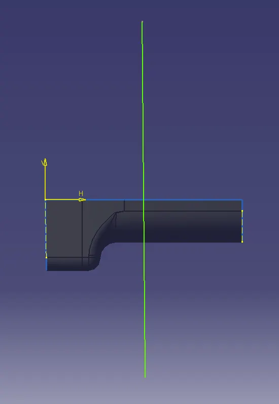
Fig 2b – PARTIAL TOOLING AXIS SKETCH
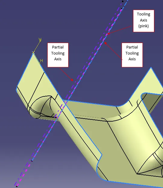
Fig 2c – TOOLING AXIS (Bisecting the Sketch Lines)
Thickened Part
After creating the Tooling Axis, we then thickened the Drill Handle based on the completed Bezel Class A, B and C surfaces. We next added ribs, and finally screw bosses according the respective design rules.
Feature Tree
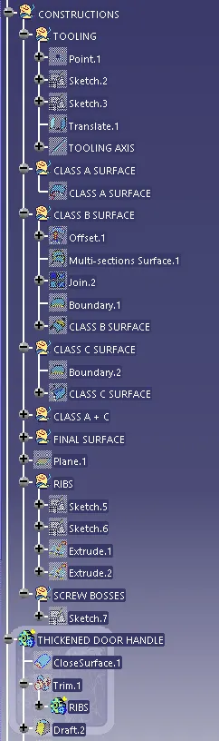
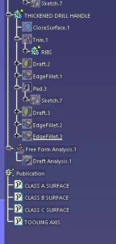
Fig 3 – Feature Tree
VIEWS & DRAFT ANALYSIS
Below are four views of the final component (Iso, Front, Side, Top), using 0.5-degree draft for the screw bosses and ribs (with a cutoff of 0.45-degrees in the Draft Analysis Tool):
Iso
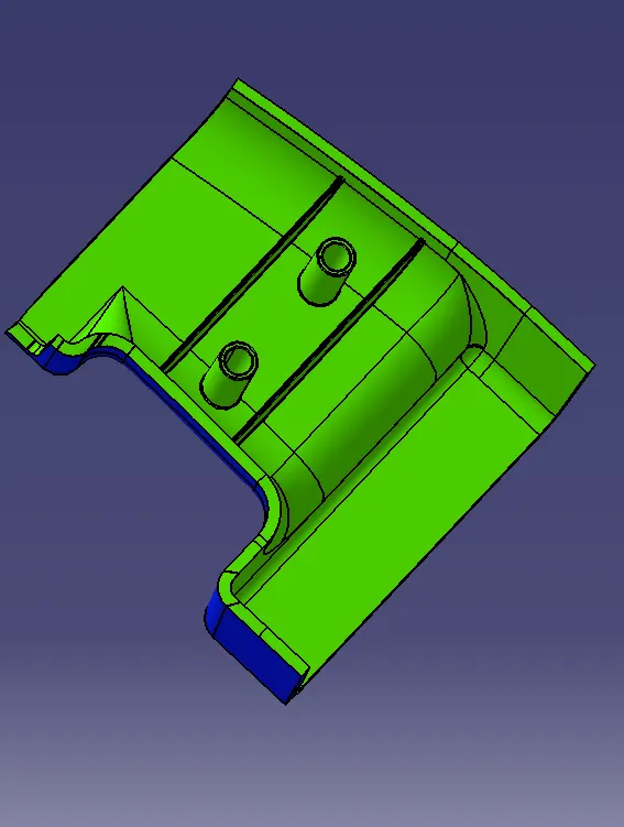
Fig 4a - Iso
Front
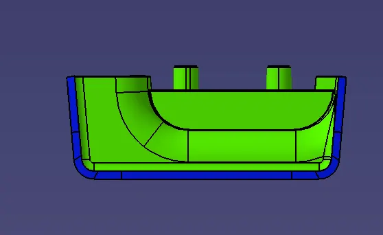
Fig 4b - Front
Side
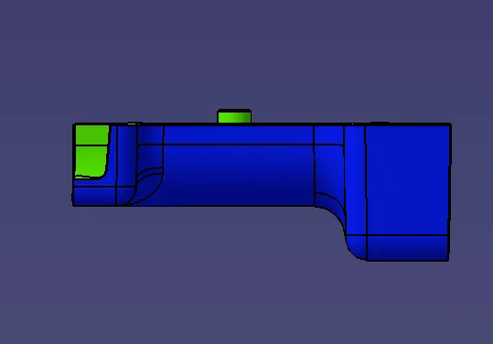
Fig 4c - Side
Top
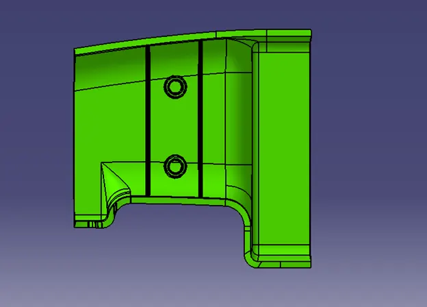
Fig 4d – Top
The Draft Analysis as shown above generally validated the design for manufacturability.
Conclusion: We were able to successfully model the thickened Drill Handle with Ribs and Screw Bosses and generally verified the component for Draft Analysis.