Hood design-Week 2
HOOD ASSEMBLY PROJECT
Objective
To design a hood inner panel (“HIP”) and assemble it with a hood outer panel (“HOP”), Hinges, Striker, and Reinforcements to create an automobile hood.
Software Used
SIEMENS NX CAD Student Version
Hood
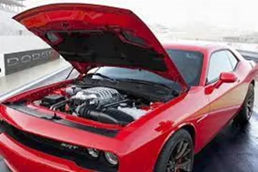
Fig. 1 - Hood with Gas Stays
An automobile hood is made up of an inner and an outer panel. The inner panel serves as the structural support, while the outer panel, also referred to as the “skin,” provides the aesthetic appearance for the vehicle. The hood also contains hinge assemblies, to allow for an open/close motion, and a striker and latch to allow the hood to be secured shut. The latch mechanism is typically triggered in a two-step process, in which a release lever inside the automobile cabin releases the latch just enough for a person opening the hood to insert their fingers under the hood to activate the latch and open the hood fully.
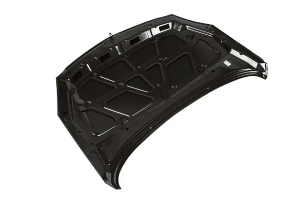
Fig 2 - GM Hood Assembly, showing Inner Panel
The hood may be kept open either by a support rod, or with a pneumatic gas stay.
Safety requirements
The hood must meet several safety requirements and criteria. For driver safety, the hood should transfer the force of a frontal collision along the side panels of the car, and not into the passenger cabin. It should also collapse during a frontal or side impact, to absorb as much force of the collision as possible.
For pedestrian safety, the hood inner panel should also be designed to minimize the effects of collision with a pedestrian. In particular, if a pedestrian, whether adult or child, is struck head-on and is thrown onto the hood, the hood should collapse to absorb as much impact force as possible. As average body height varies by region, hoods in different regions may have different inner panel designs to provide maximum safety to pedestrians in the target regions.
Various safety standards measure hood safety from the standpoint of the pedestrian. In Europe, the standard is called Euro NCAP.
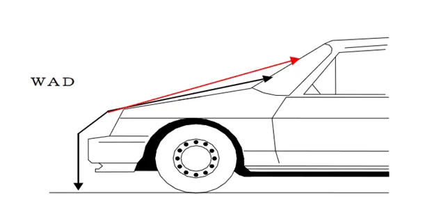
Fig 3a - Wraparound Distance (“WAD”), indicating where a head impact may occur
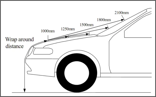
Fig 3b - Wraparound Distance (“WAD”), based on assumed height of pedestrian
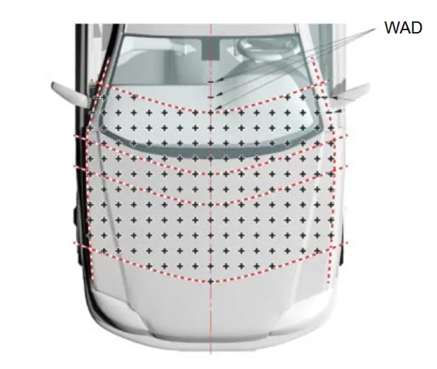
Fig 4 - Impact points on the front of the vehicle
COMPONENTS USED IN HOOD ASSEMBLY
Striker
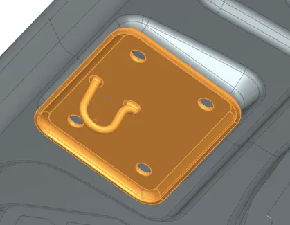
The striker engages with the latch on the engine frame to fasten the hood closed. When the latch is released from the striker, the hood is free to open.
Fig 5 - Striker
Hinge Assembly
The hinge assemblies attach the hood to the frame around the engine compartment and allows the hood to swing open or shut.
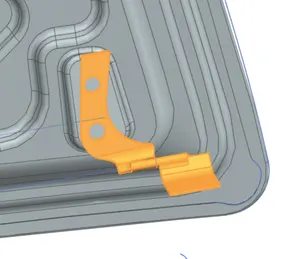
Fig 6a – Hinge Assembly
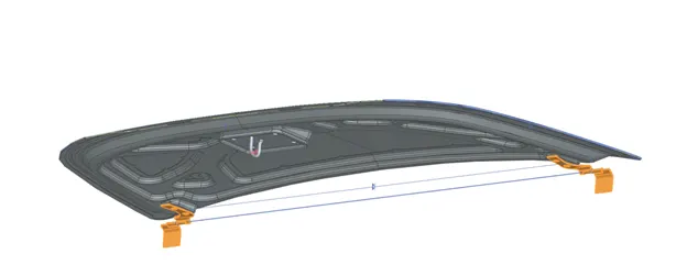
Fig 6b – Left and Right Hinge Assemblies
Hood Outer Panel
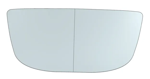
Fig 7 – Hood Outer Panel
The outer panel is the visible surface on the vehicle. Designed for styling and aesthetics, it is painted and typically clear-coated. Given its smooth, aesthetic finish, it cannot have weld points, bolts or rivets showing, and thus must be attached to the inner panel through hemming and mastic seals.
Hood Inner Panel
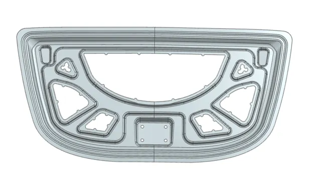
Fig 8 – Hood Inner Panel
The hood inner panel provide structural support to the hood. It also helps channel forces from crash impact away from occupants in the car, as well as provide a collapsible surface in the event of collision with a pedestrian.
Mastic Seal Pads
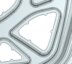
Fig 9 – Mastic Seal Pads
The mastic seal pads hold the mastic sealant used to adhere together the hood inner and outer panels. The mastic sealing provides rigidity and vibration resistance to the hood.
Additional Hood Parts (not contained in this Hood Assembly)
Support Rod
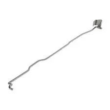
Fig 10 - Aftermarket Automobile Support Rod (Walmart)
The support rod is usually mounted inside the engine compartment, affixed either to the hood inner surface or to the frame surrounding the engine housing. The support rod should contain bends for additional rigidity. The support rod should be positioned opposite the battery side of the car so as to avoid obstructing access to the battery.
Gas Stay
A gas stay can also serve the same function as a support rod, i.e., to keep the hood open. It can also assist in opening the hood, therefore requiring less force applied by the person opening the hood. The gas stay uses compressed gas to apply force between the hood and frame.
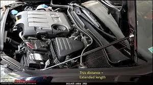
Fig 11 – Gas Stay
Parts of Hood used in Hood Assembly
Key parts:
* Striker
* Hinge Assembly
* Hood Inner Panel
* Hood Outer Panel
Key parameters:
* Hood Inner Panel thickness: 0.75mm
* Hood Outer Panel thickness: 0.75mm
* Intra-panel Glue Clearance: 0.20mm
* Striker and Hinge Reinforcement thickness: 1.5mm
* Rear-relief minimum distance: 2.93mm
* Front-relief minimum distance: 3.07mm
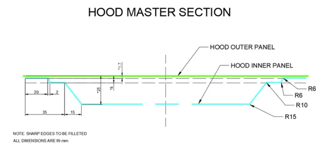
Fig 12 – Cross Section
Hemming Guidelines:
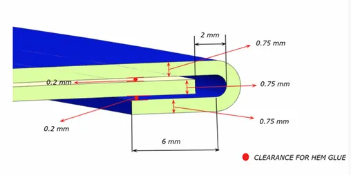
Fig 13a – Hemming Guidelines
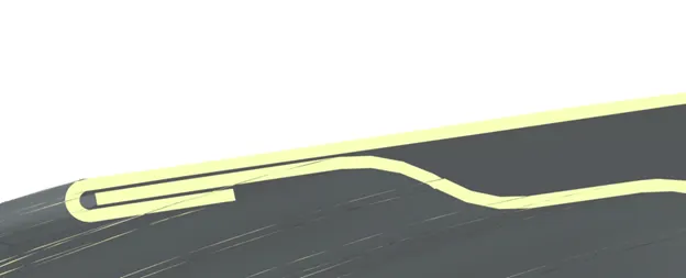
Hemming actual result:
Fig 13b – Hemming Actual Result
Rear Relief:
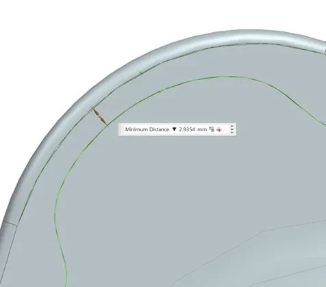
Fig 14 – Rear Relief
Front Relief:
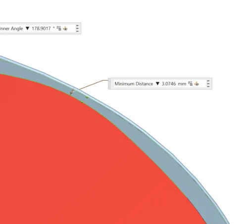
Fig 15 – Front Relief
Manufacturing Process
The manufacturing process for the hood assembly relies on three main techniques. First, the HOP and HIP are formed through a deep drawing process, which presses sheet metal into the desired shape. After deep drawing, the pieces are then further processed to remove areas, complete edges and achieve other features. The second technique involves Mastic Sealing, where elastic reinforcing compounds are used to glue together the HOP and HOP to provide structural rigidity. The final manufacturing step in assembly involves hemming together the HOP and HIP. Often, hemming can include gluing, riveting, or spot welding.
Deep Drawing
In the Deep Drawing process, sheet metal blank is deformed in a punch-and-die tool. The punch presses the blank into the die, transforming its shape. The process is considered “deep” drawing when the depth of the final part exceeds its diameter. The target sheet is fixed in place between a binder, or blank holder, and the die.
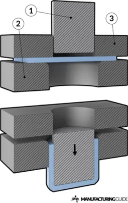
Fig 16 – Deep Drawing
Mastic Sealing
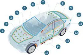
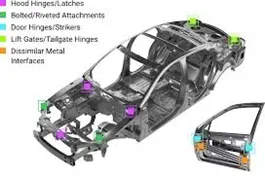
Fig 17a and 17b – Mastic Sealing
Mastic sealing involves the application onto adhesion pads of a sealant. The aim is to flexibly adhere the HOP and HIP and provide a firm, elastic bond between the two surfaces. Doing so adds rigidity to the hood assembly, while also reducing vibration and noise. Typically the sealing compound is a liquid or paste that cures through a heating process. Many different compounds can serve as sealants, including Polyurethane and Silicone among others. As the HOP is an aesthetic surface, it cannot be fixed to the HIP through welding or bolting, and thus must rely on mastic sealing and hemming for attachment.
Hemming
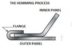
Fig 18 – Hemming Diagram
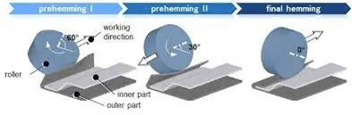
Fig 19 – Hemming Process
Hemming is a process for joining two surfaces. In the hemming process, a flange on the outer panel is bent and pressed against an inner panel, fixing the two panels together. The process of bending and pressing the flange is achieved through a series of rolling operations.
FINAL HOOD ASSEMBLY
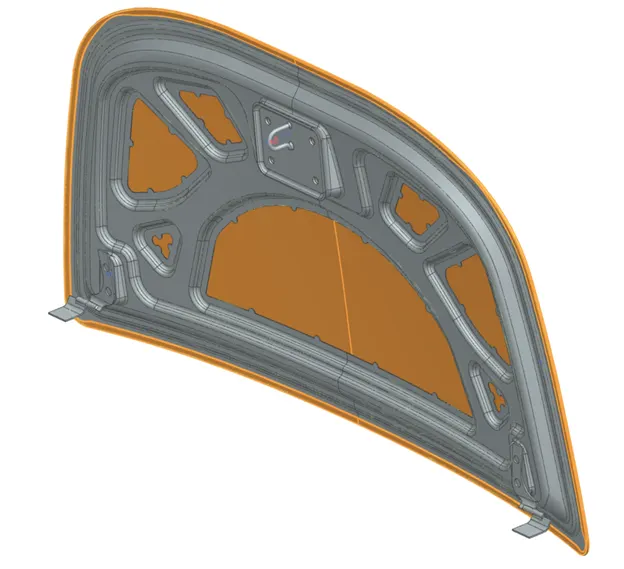
Fig 20a - Iso
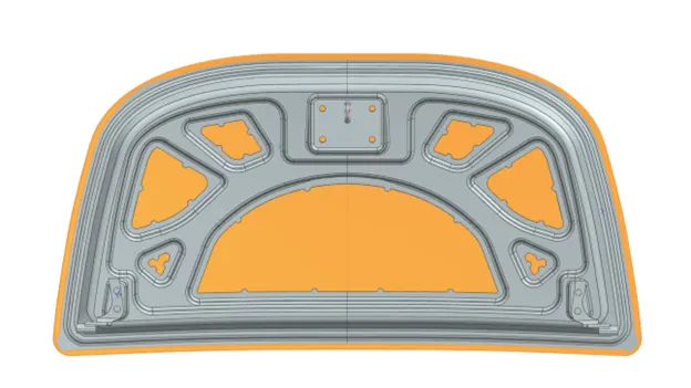
Fig 20b - Bottom
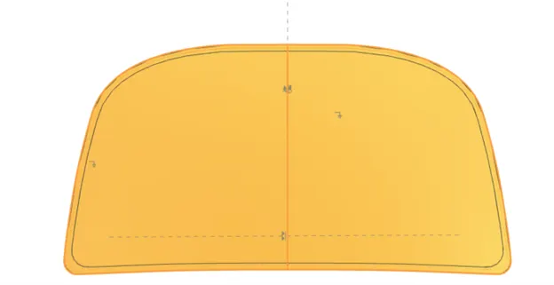
Fig 20c -Top
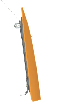
Fig 20d - Side
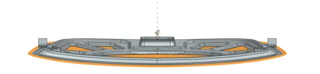
Fig 20e - Front edge
TREE STRUCTURE
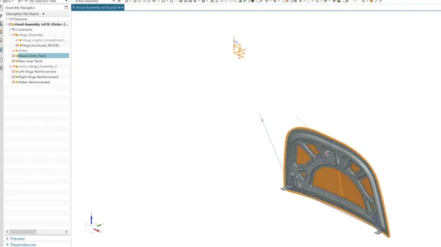
Fig 21 – Tree Structure
Tree Structure with Constraints:
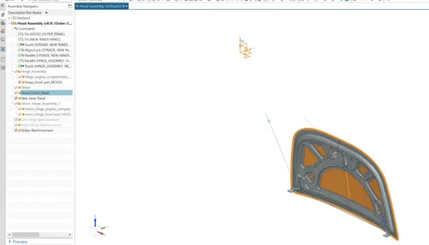
Fig 22 - Constraints
Conclusion
Based on the methodology described above, the Hood Assembly was successfully completed.