Radar Mast & Final Assembly of Yacht
Radar Mast (Front, Side, Iso, Top)
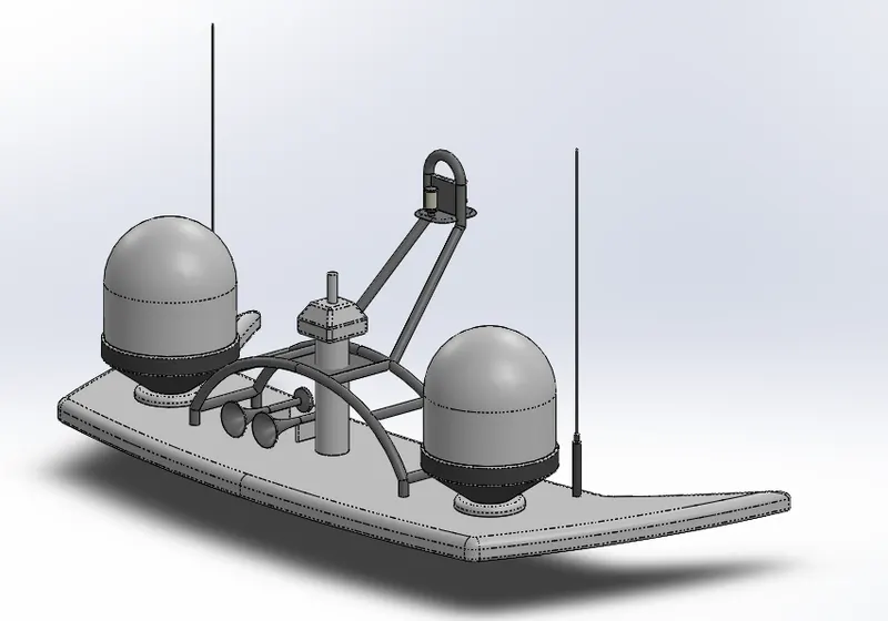
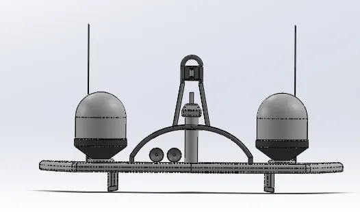
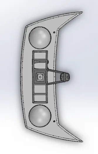
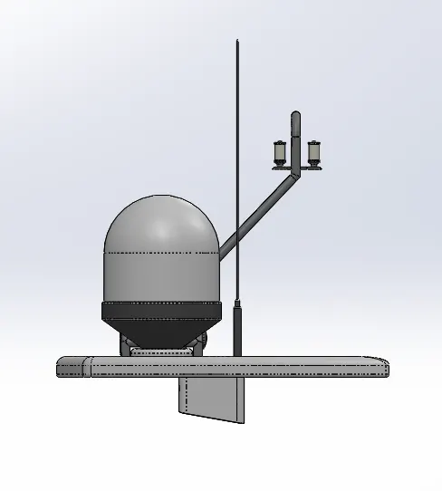
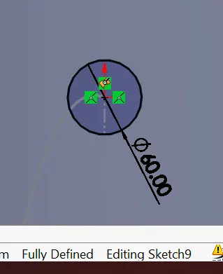
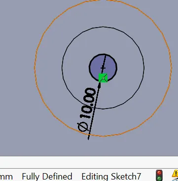
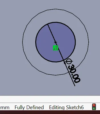
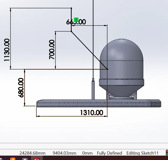
Radar Mast (Sketches)
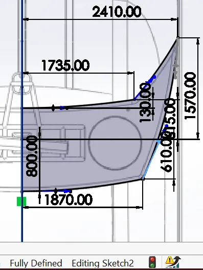
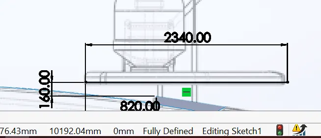
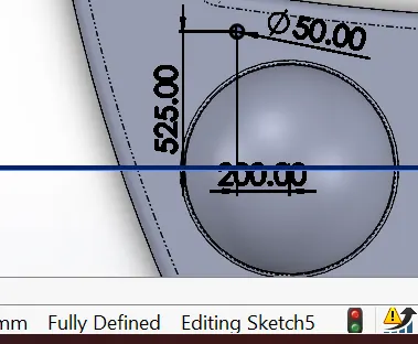
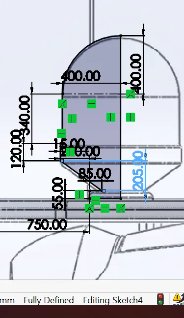
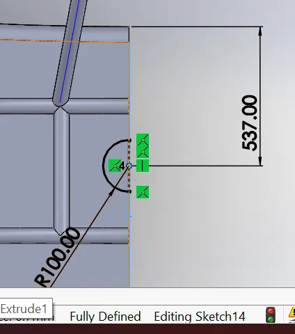
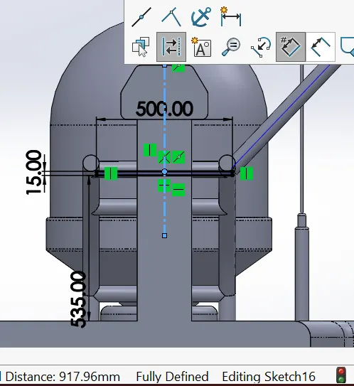
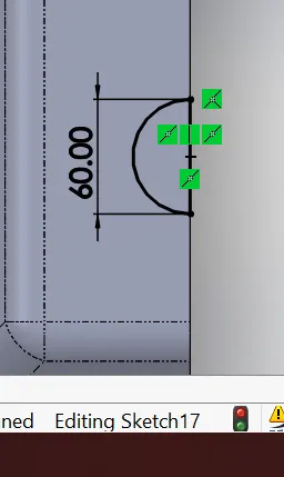
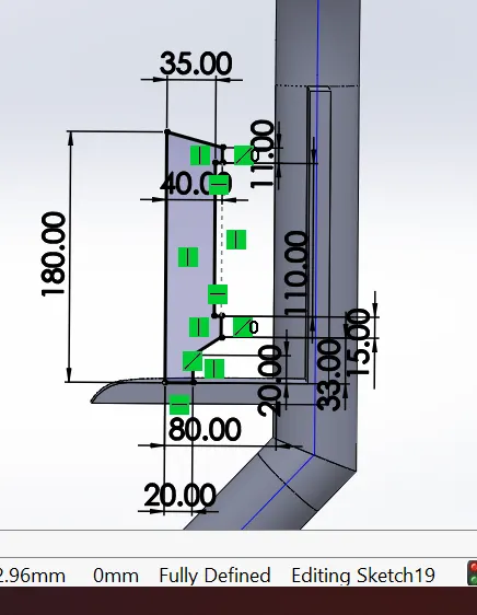
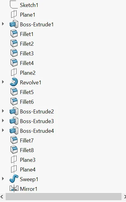
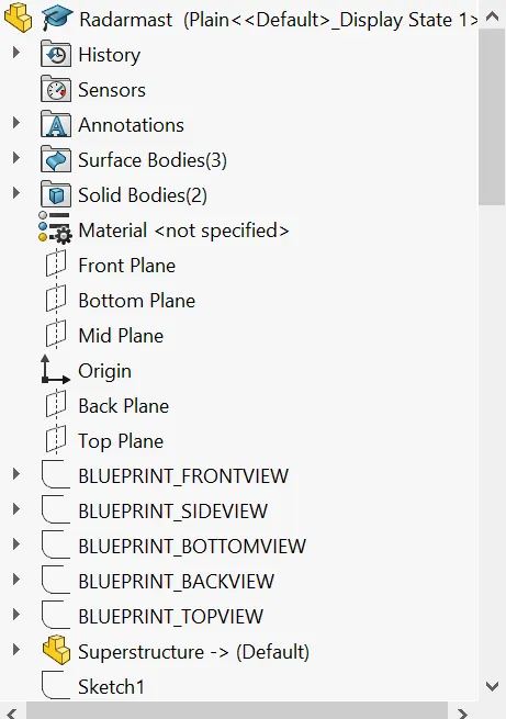
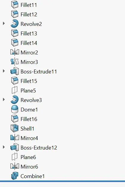
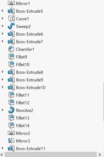
Radar Mast (Feature Tree)
YACHT ASSEMBLY REPORT (Includes Renders/Mates)
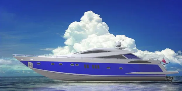
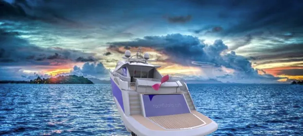
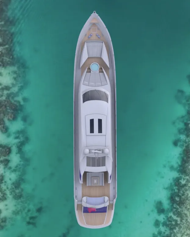
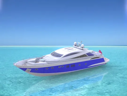
ASSEMBLY OF SUNSEEKER PREDATOR YACHT
Objective:
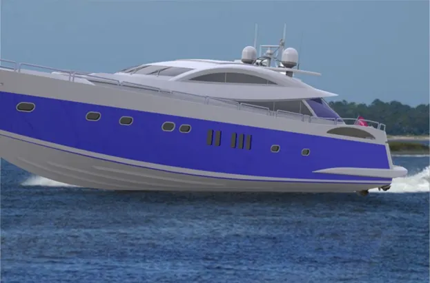
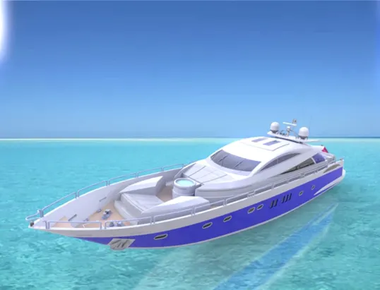
The objective of this project was to use Solidworks to model in 3D a pleasure yacht, the Sunseeker Predator.
Introduction:
This report details the methodology used to model the Sunseeker Predator motor yacht using Solidworks. The approach and methodology is contained in the following sections, which contain details regarding the design features and tools used to produce each of the parts in the final Assembly. These parts include the: Radar, Propeller, Hull, Front, Mid and Rear Seats, Superstructure, Radar Mast, and Garage Door.
OVERALL DESIGN PROCESS
The design process began with Blueprints, as below which were added as Sketch Pictures to initial Blueprint Sketches. Based on the Blueprints, the Part design commenced. First was the Radar. This was followed by the Propellers. Next came the Hull, followed by the Garage Door. Once the Hull was complete, the Front and Mid and Rear Seats were added. Next came the Superstructure, and finally, the Radar Mast.
Tools used:
Line – a straight line typically used to sketch edges.
Centerpoint line – a construction line, typically used as a guide or axis for rotation
Circle – a circle with center, typically used to sketch holes and outlines. Centerpoint circles were used.
Arc – a portion of a circle, with a center of revolution and a radius. Centerpoint and 3-point were used.
Rectangle – a tool with four sides and perpendicular angles between adjacent sides. Centerpoint and Three-point rectangles were used.
Spline – a tool to draw smooth curves.
Slot – a tool to draw a slot shape, in this case used to sketch windows and connecting pieces.
Ellipse – a tool to draw an Ellipse, in this case used to make parts of the benches on the deck
Offset Entities – a tool to replicate edges in a sketch, offset by a given distance.
Convert Entities – a tool to bring external geometries into a given sketch.
Trim Entities – a tool to trim excess geometry in a sketch
Extend Entities – a tool to extend geometries in a sketch
Mirror Entities – a tool to copy and mirror a geometry in a sketch
Fillet Sketch – a tool to fillet sharp corners in a sketch
Pattern Entities – a tool to create patterns (in this case linear or circular) in a sketch.
Features used:
Sketch plane – a plane on which to sketch a part
Sketch – a two-dimensional or three dimensional representation of a part, body, object or geometry
Extruded Boss/Base – a linear extrusion into three-dimensional space of a two-dimensional sketch region or contour
Revolved Boss/Base – a revolution into three-dimensional space of a two-dimensional sketch region or contour
Swept Boss/Base – a curved sweep along a guide curve into three-dimensional space of a two-dimensional sketch region or contour
Lofted Boss/Base – a feature to join in three-dimensional space two separate surfaces or solid bodies
Extruded Cut – a feature to linearly remove from a solid body three-dimensional geometries defined by a sketch region or contour.
Revolved Cut - a feature to remove from a solid body along an axis of revolution three-dimensional geometries defined by a sketch region or contour
Fillet – a feature to round sharp edges in a three-dimensional model
Chamfer – a feature to bevel the edges in a three-dimensional model
Pattern – a feature to copy and evenly distribute (either linearly or in circular fashion in this case) three-dimensional geometries
Shell – a feature to hollow out a solid body, leaving the walls of the body at a specified thickness
Mirror – a feature to copy and mirror three-dimensional geometries
Project Curve – a feature to combine two two-dimensional curves to create a single three-dimensional curve
Split Line – a feature to divide a sold body into separate regions
Combine – a feature to combine two separate solid bodies into a single body
Split – a feature to divide a sold body into separate solid bodies
Dome – a feature to add roundness to a flat face on a solid body
Surfaces used:
Extruded Surface – a feature to use lines in a two dimensional sketch to linearly create a two-dimensional surface in three-dimensional space
Revolved Surface - a feature to use lines in a two dimensional sketch to revolve a two-dimensional surface in three-dimensional space
Swept Surface - a feature to use lines in a two dimensional sketch and a guide curve to create along a path a two-dimensional surface in three-dimensional space
Lofted Surface – a feature used to connect two separate surfaces
Filled Surface – a feature used to fill gaps in a set of surfaces
Offset Surface – a feature used to copy and offset a surface
Ruled Surface – a feature used to extend
Fillet – a features used to round the sharp corners where two surface faces meet
Delete Face - a feature used to remove a surface face
Extend Surface – a feature used to achieve a best fit in extending a surface past its initial boundary(ies)
Trim Surface – a feature used to reduce the size of a surface by removing material
Knit Surface – a feature used to combine two or more surfaces into a single surface
Reference Plane – a feature used to mirror surfaces or on which to sketch surfaces
Split Line – a feature used to divide surfaces along a cutting tool line
Project Curve – a feature used to combine two two-dimensional curves into a single curve in three dimensions
Assembly features and tools:
Insert components
Mate
Blueprints
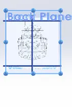
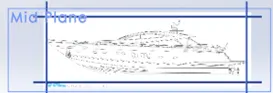
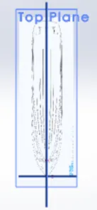
We started by importing sketch pictures into sketches on five planes: Top, Bottom, Mid, Front and Back.
PROPELLER
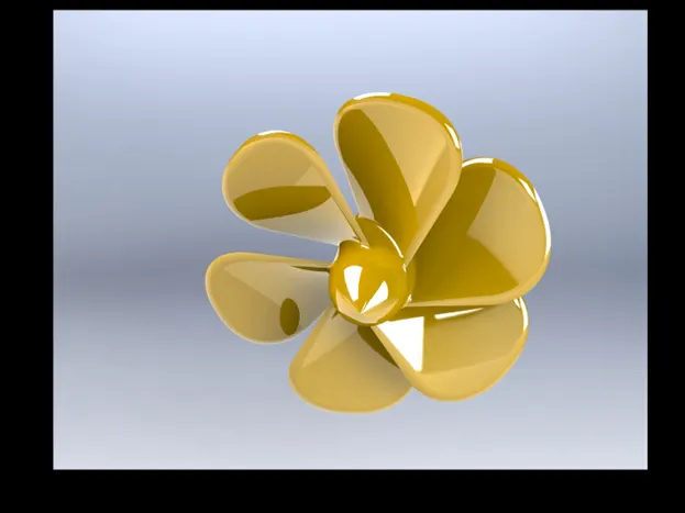
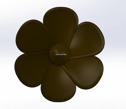
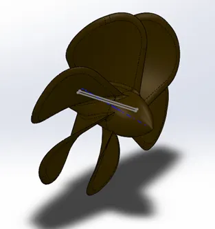
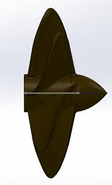
The first part we created was the propeller. To do so, we used the following features and tools: Sketch, Revolve, Fillet, Extrude Boss/Base, Extrude Cut, and Circular Pattern.
We began with the hubshaft. This was created by revolving a sketch. We then added the blades lofting a sketch and then using a circular pattern to position the blades around the shaft. We also filleted the blades to round the edges, and in general filleted all the sharp edges. Lastly, we applied the appearance
RADAR
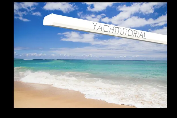

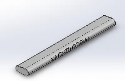
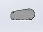
For the radar, we used the following features and tools: Sketches, Extrude, Fillet, Cut Extrude, Sketch Pattern, Mirror and Split Line. Here, we extruded a trapezoid shape, and filleted the shape. We then offset the end and extruded further to form the endplates. We then used offset to create a path around the end plate to situate the bolts, and created the first bolt. We extrude-cut a hexagonal cavity into the bolt, and then patterned the bolt to points we positioned along our sketch path. We next mirrored the end plate, cut-extruded the mounting hole, and then used Split Line to create text on the outer surface.
HULL
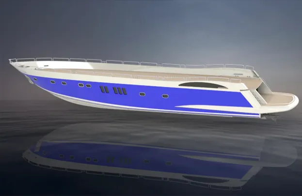
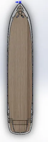
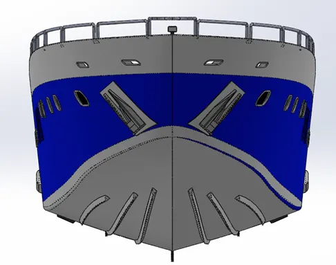
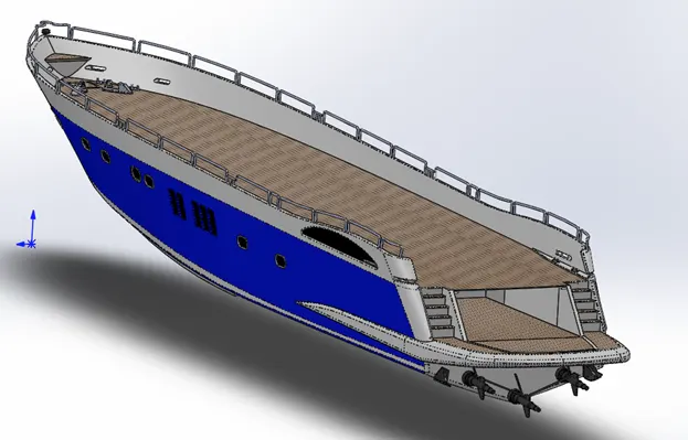
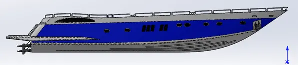
The Hull used the following tools: Sketch, Extrude, Extrude-Cut, Shell, Surface Extrude, Surface Revolve, Surface Fill, Surface Loft, Surface Sweep, Knit Surface, Surface Trim, Surface Extend, Surface Fill, Ruled Surface, Linear Pattern, and Mirror.
The hull was mainly created by mirroring two half-hulls. The first half hull was created mainly by sweeping sketch curves along projected curves to create surfaces. The surfaces were modified where necessary by trimming and adding split points. Windows and other features were extrude-cut into the hull. Railing and benches were swept. Surfaces were knit together where appropriate to create a solid body, out of which the garage space was split and saved separately. The remaining hull was then shelled and stairs were added. We also offset a reference surface to the top of the hull, for positioning additional parts onto the hull in subsequent steps.
GARAGE DOOR
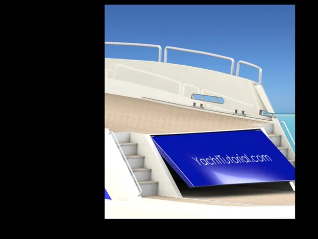
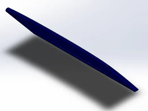

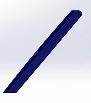
For the Garage Door, we use the following tools and features: Sketch, Extrude, Extrude Cut, Fillet,
Shell, and Mirror. First, we import the Garage space, which represents half of the final garage. Then we perform Cut-Extrude to reduce the garage space it to roughly the size of the door. We then shell it, fillet and cut out hinge holes. We then mirror the door across the mid-plane to yield a full-sized door. Lastly, we Extrude-Cut the test onto the front surface.
FRONT SEAT
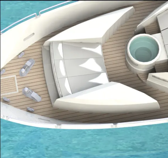
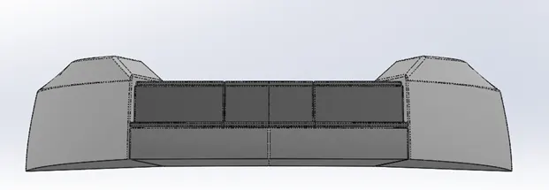
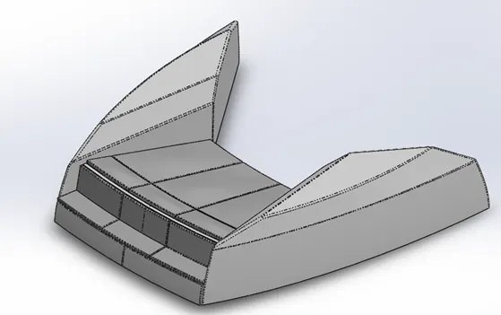
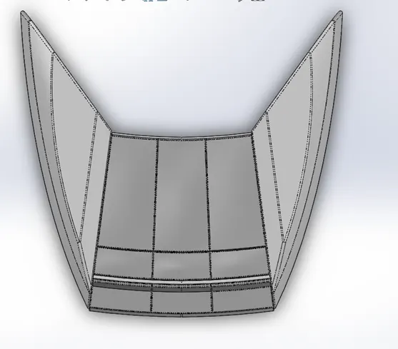
For the front seat, we use the following tools and features: Sketch, Surface Sweep, Surface-Extrude, Surface-Trim, Surface-Loft, Body Delete/Keep, Surface-Knit, Surface-Fill, Fillet, Chamfer, Revolve, Cut-Extrude, Cut Extrude-Thin, Mirror, and Dome.
We start by importing the hull surface as a reference, and then sweeping out a surface for the side of the seats. We then extrude additional surfaces from the sweep, trim excess material, and surface-fill the gaps. We then trim openings in the top and bottom surfaces, loft to close openings, and Body-Delete excess material. Next, we knit surfaces, fill holes, and chamfer. This creates one of the end-pieces.
We then revolve out the center base, and cut-extrude it to the appropriate dimensions. We do the same with the mattress on top. We apply thin cut-extrudes to divide the mattress into two side-by-side mattresses. We then fillet extensively, mirror the half-seat across the mid-plane, dome the mattresses to provide an appearance of padding, and apply final fillets.
MID SEAT
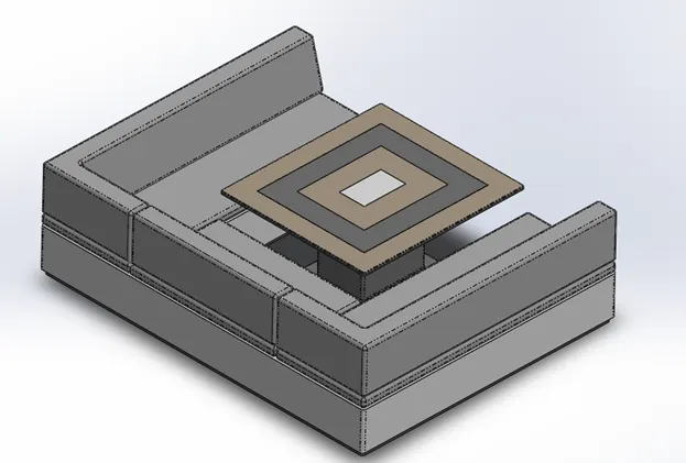
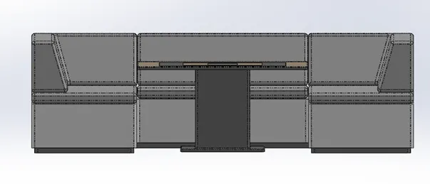
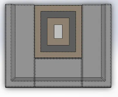
For the mid-seat, we use the following tools and features: Sketch, Extrude, Chamfer, Fillet, Mirror, and Cut-Extrude. We begin with the imported hull surface. We then extrude the half seat base. cushions and backings on top of the hull. We apply chamfers and fillets, and then mirror the half seat across the mid-plane. We then extrude the table, and extrude-cut the pattern on top.
REAR SEAT
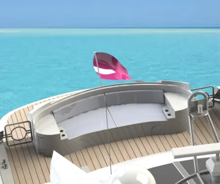
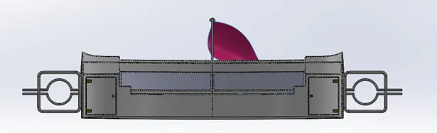
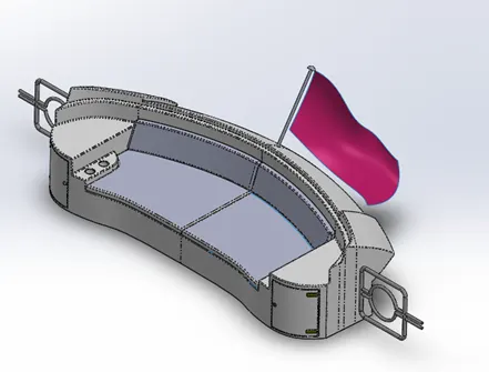
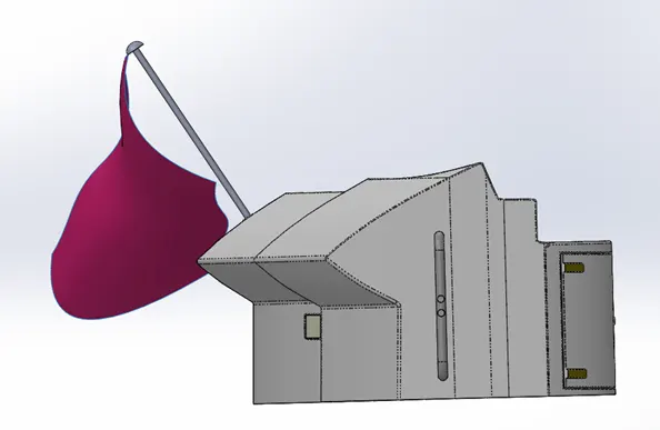
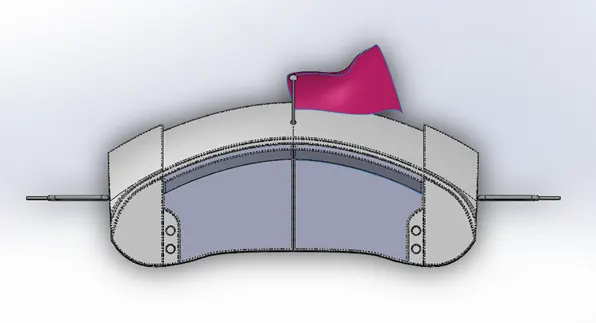
For the reat seat, we use the following tools and features: Sketch, Planes, Surface-Sweep, Surface-Offset, Surface-Trim, Ruled-Surface, Surface-Knit, Surface Extrude, Surface-Loft, Extrude, Extrude-Cut, Chamfer, Fillet, Sweep, Mirror, Combine, and Revolve.
We begin by performing a Surface-Sweep to create the outer surface of the backing geometry. We then offset this and Trim (to stagger the sides), Rule out the surface, and then knit. We then trim, sweep out the upper ledge, extend the ledge and trim it, extrude the surfaces, trim and knit fill out the outer seat backing, then loft to close gaps. Next, we extrude to form the inner surface of the seat backing. We then Loft to enclose the bottom of the seat backing. We then extrude out the seat base, sides, armrests, and cabinet doors. We extrude-cut drink holders into the armrests, and add the hinge and lock hardware with Boss-Extrude.
Next we offset the top surface of the base, and extrude the cushions and seat backing, using extrude cuts to divide the cushions and backing. We also apply fillets where appropriate. We next Sweep out the side rails half patterns, then mirror these. We then mirror the half-seat about the mid-plane, and combine all the bodies.
Lastly, we revolve the flag pole, and surface-loft the flag using four 3D sketches representing the edges of the flag.
SUPERSTRUCTURE
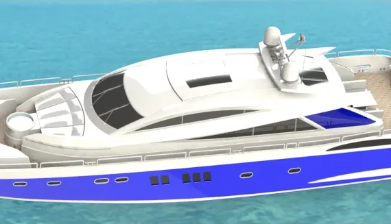
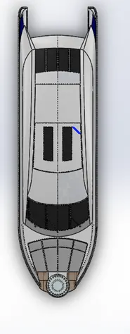
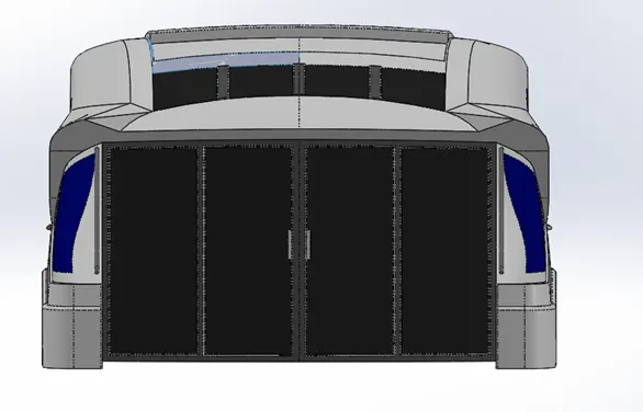
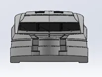
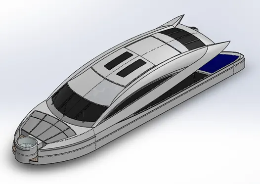
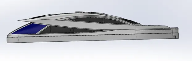
For the Superstructure, we use the following tools and features: Surface-Extrude, Surface-Knit, Ruled Surface, Fillet, Surface-Trim, Surface-Loft, Surface-Sweep, Surface-Fill, Project-Curve, Surface-Extend, Extrude, Extrude-Cut, Delete Face, Surface Thicken, Dome, Mirror, Chamfer.
We start with a surface extrude and sweep to create the base wall for the superstructure. We apply a ruled surface and trim to create the correct geometry. We then create projected curves for the upward swept “swoosh” wall member and use Surface-Fill to create the “swoosh”. We fill in walls to the sides of the superstructure using sweeps and trims. We add the upper flooring with a surface-extrude. We loft out the rear support wall, and project curves to create a loft for the roof arch, with further lofts to fill out the roof.
We use ruled surfaces and surface-extends to create the side window walls, and the rear overhang covering the mid-seat. We use surface-extrude to construct the rea wall, which will later become glass doors. We use surface extend and surface fill to fill in gaps. We then use more surface extrudes, sweeps, extends, and cuts to fill out the front jacuzzi deck. We even Delete Face to remove the face of the half-jacuzzi on the mid-plane. We create a solid half-superstructure, and create an offset surface on the jacuzzi deck on which to place deck mattresses. We use surface extrude and surface cuts to create the mattresses. We then dome them to provide the appearance of cushioning.
We use sweeps to add railing along the jacuzzi deck and back stairs. We use thin extrudes and cut extrudes to create the back doors and hinge/handle hardware. We use extrudes and extrude cuts to form the front windshield panels and roof window panels. We use extrudes to create the windshield wiper posts and we mirror across the mid-plane to create the full superstructure. We offset the roof surface to create a reference for the Radar Mast. We then use extrudes, cuts and chamfers to create the windshield wipers.
RADAR MAST
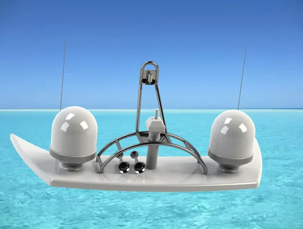
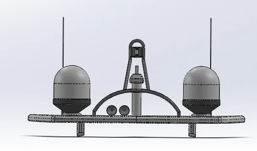
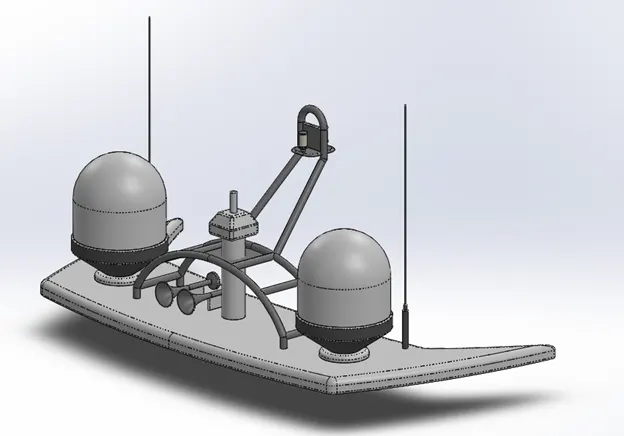
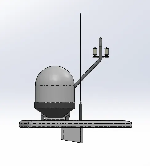
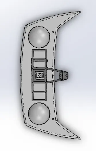
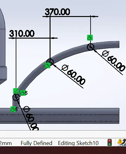
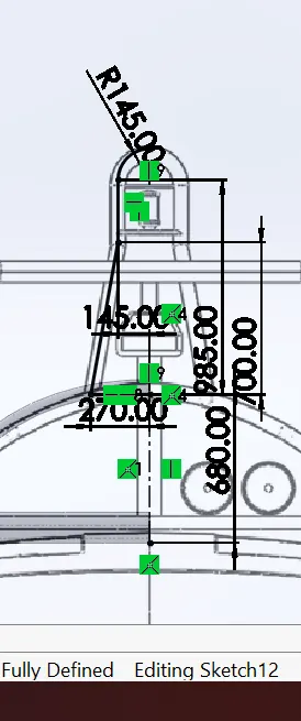
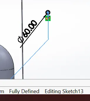
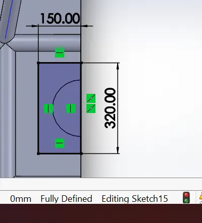
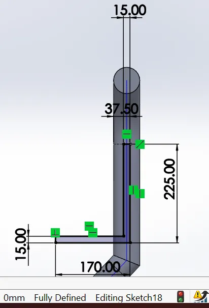
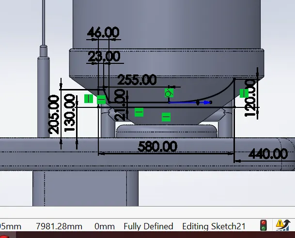
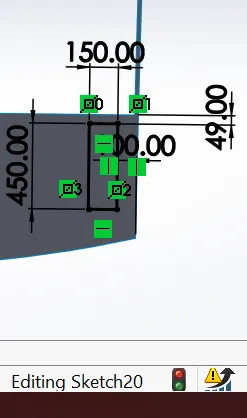
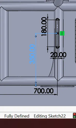
The Radar Mast uses the following features and tools: Sketch, Extrude, Revolve, Fillet, Chamfer, Project Curve, Sweep, Mirror, Surface-Mirror, Dome, and Combine. We start by extruding the half-base of the mast, and then fillet the half-base. We then construct the radar dome with a revolve. Next, we extrude the antenna aerial, and then sweep and extrude the supports for the curved frame structure. We project curves to provide the guide curve for a sweep of the upper frame to hold the lights. We then extrude the radar support post and the lighting platform. We create a lightbulb using a revolve and mirror it about a local plane to create the second lightbulb. We extrude platform supports, revolve and shell the a horn, then mirror the horn. We then extrude supports for the horn, then mirror the other half of the Radar Mast and Combine into one body.
ASSEMBLY
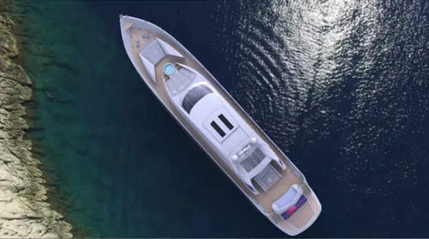
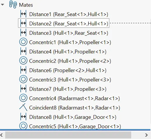
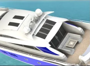
For the Assembly, we bring in the hull, and then situate the rear seat using Distance/Coincident constraints. We bring in the propellers and use concentric and coincident constraints to position these on the propeller shafts. We bring in the superstructure and front and mid seats, which are automatically positioned on the hull, and then bring in the radar mast, which positions automatically on the superstructure. We then use concentric and coincident constraints to constrain the radar on the radar mast, and finally use coincident and concentric constraints to constrain the garage door.
CONSCLUSION:
The methodology in this report was followed faithfully and resulted in a successful design, model and assembly of a model of the Sunseeker Predator Yacht.