Week 9 - Attachment Feature Creation (Ribs & Screw Boss) - Challenge 1
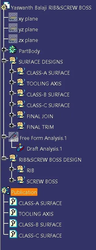
STRUCTURE TREE:
POSITIONED SKETCH:
SKETCH-1
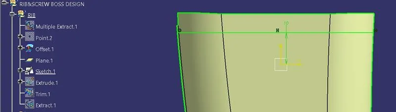
SKETCH-2
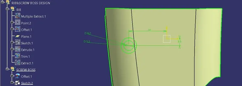
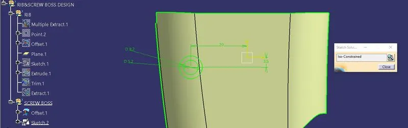
ISO-CONSTRAINED SKETCH:
SKETCH-1
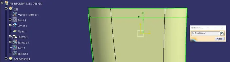
SKETCH-2
REFERENCE SURFACE:
- ISOMETRIC VIEW
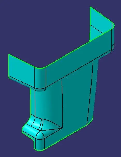
- FRONT VIEW
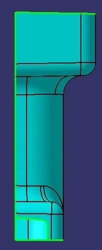
- LEFT-SIDE VIEW
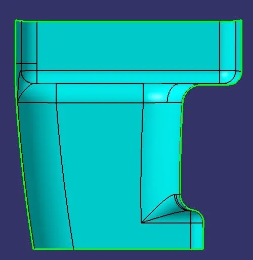
- TOP VIEW
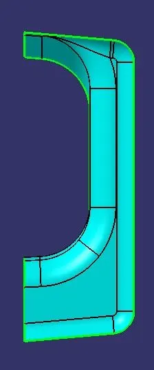
RIB & SCREW BOSS DESIGN:
- ISOMETRIC VIEW
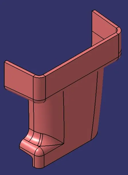
- FRONT VIEW
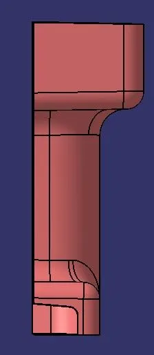
- LEFT-SIDE VIEW
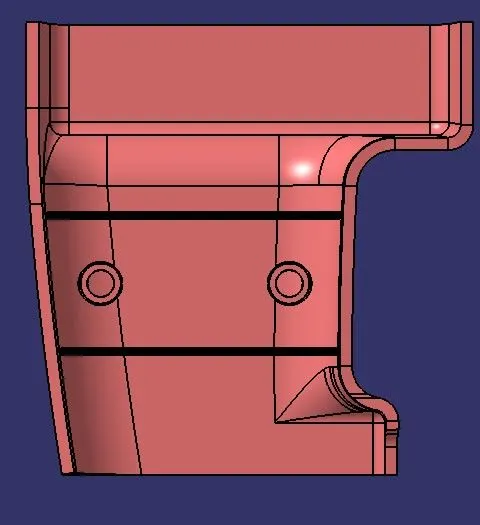
- TOP VIEW
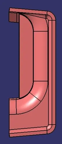
NOTE:
- Part Body THICKNESS=0.25mm
- Draft Angle=0.5 degree
- Height of Rib & Screw Boss=12.5mm
REPORT:
DRAFT ANALYSIS
NOTE:
- Due to software version issues,the draft analysis shows errors in these images.
REFERNCE SURFACE
- ISOMETRIC VIEW
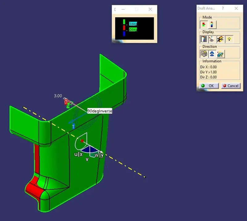
- FRONT VIEW
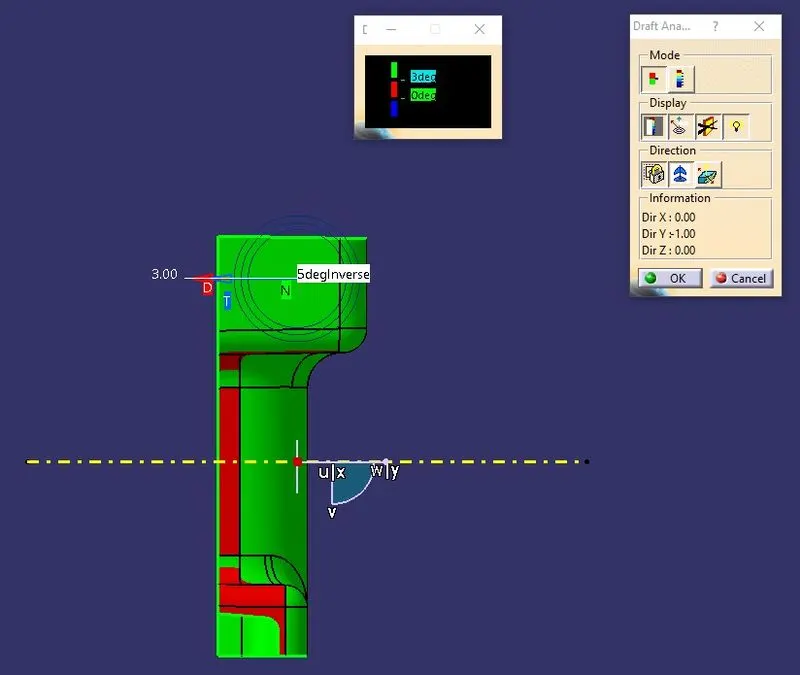
- LEFT-SIDE VIEW
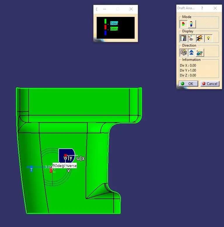
- TOP VIEW
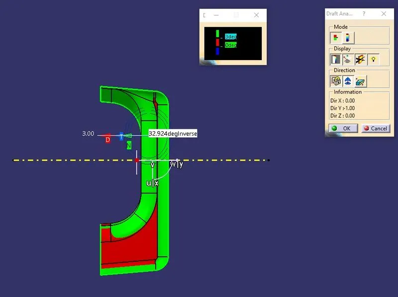
RIB & SCREW BOSS DESIGN
- ISOMETRIC VIEW
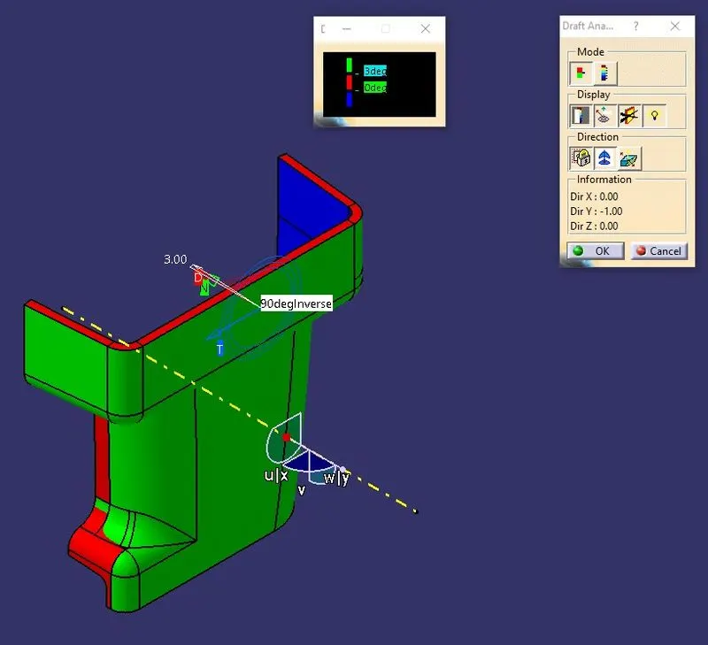
- FRONT VIEW
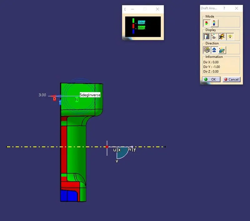
- LEFT-SIDE VIEW
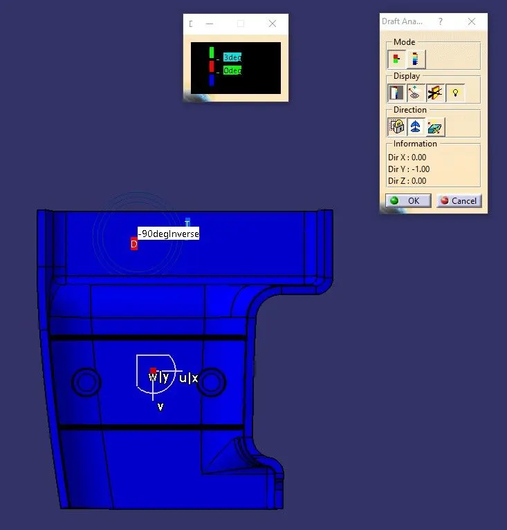
- TOP VIEW
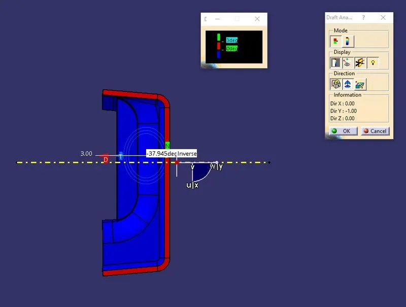
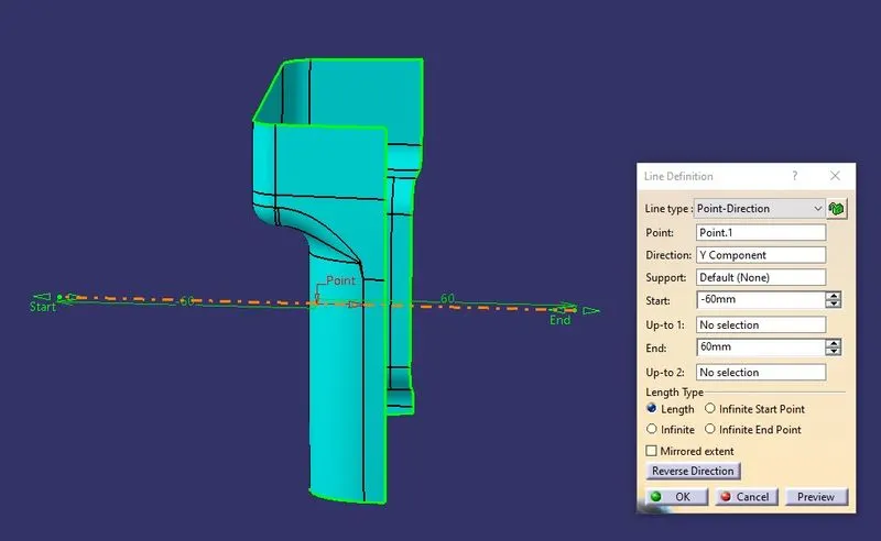
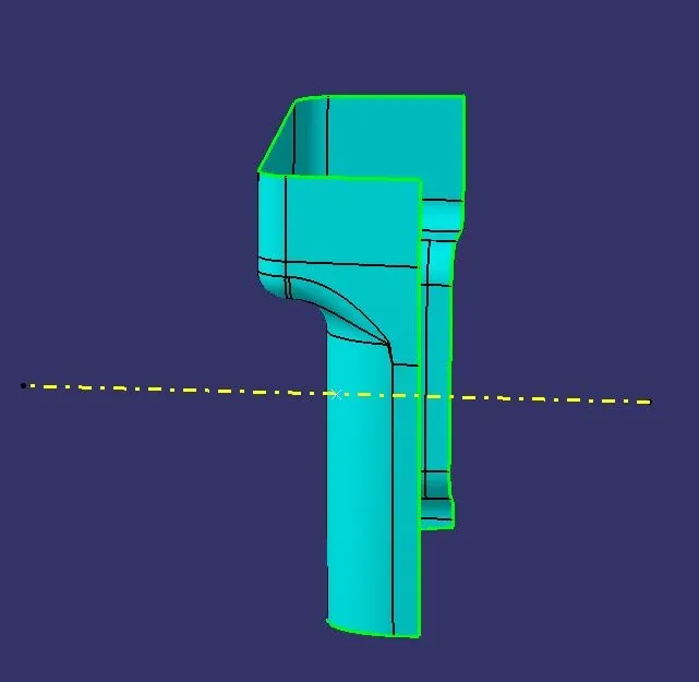
TOOLING AXIS
- Pick the direction where the reference component is seen clearly in x,y and z axises.For this component the y-axis is the best suited direction.
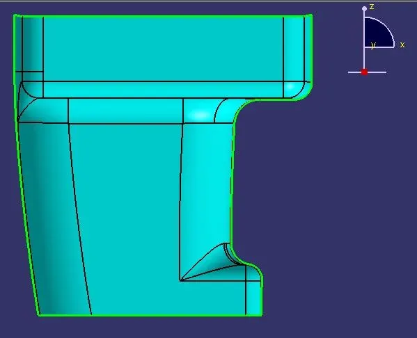
- Pick a point at the centre on the surface of the component as shown.
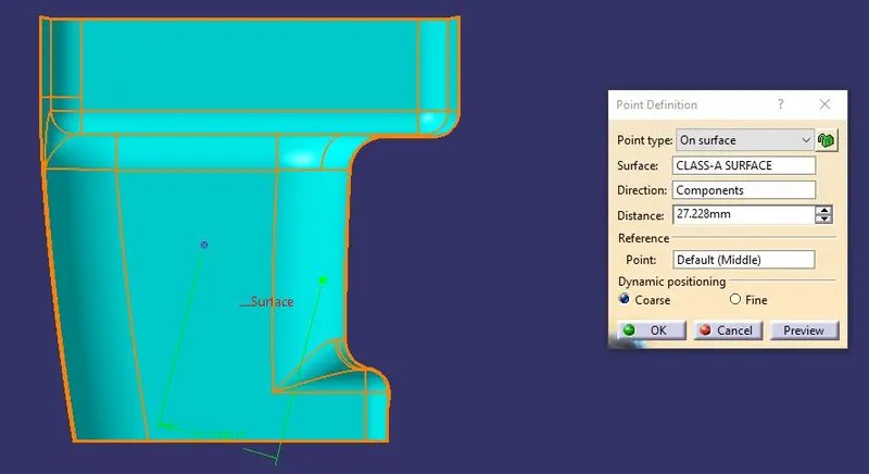
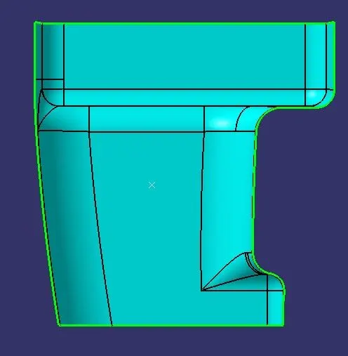
- Create a line using this point in the view direction and give the desired lenght for the TOOLING AXIS.