Week 9 - Attachment Feature Creation (Ribs & Screw Boss) - Challenge 1
Creating Ribs & Screw Boss using class a surface
Objective: Creating the plastic surface through the given Class-A surface. The tooling axis for the given Class-A Surface to be created meeting the requirements of the draft angle and at the end performing the Draft analysis on the model.
Class A surface of the Bumper is given for designing the plastic component
Class A surface
It describes the final production surface data for the part
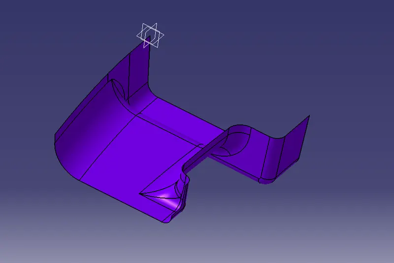
From the given Class A surface a tooling direction is created on the feasible surface. Here i have created the tooling direction at the center to the fog light area. After defining the main tooling axis draft analysis for a postive draft of 3 deg
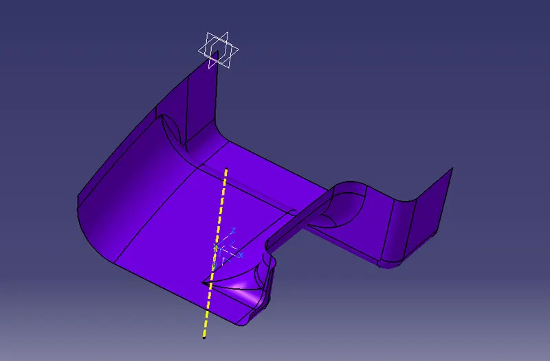
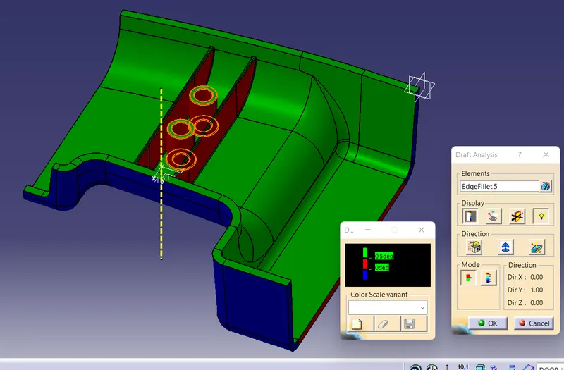
here green colour on the surface represnets that there is no negative draft.
Class B surface
To create the class B surface from Class A we have to offset the class A surface to a thickness of 2.5mm
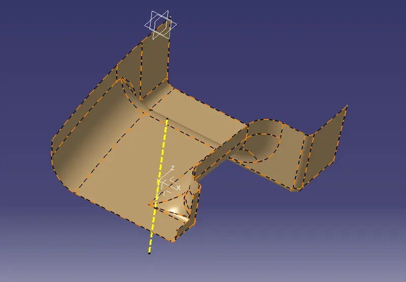
Class C surface
Extract the outer flange surface from class a and extract the border. use the sweep feature to the border at 90 deg to the surface and join with class A surface.
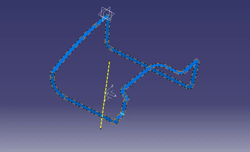
Class C surface is created
Trim the class B surface with class C surface to get the closed surface, using closed surface feature convert into solid body.
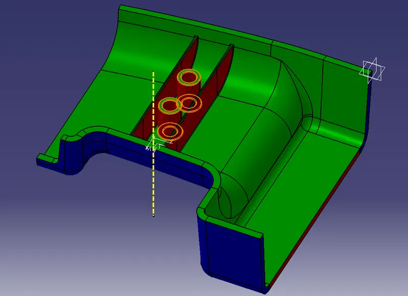
after we create a ribs and screws on solid body
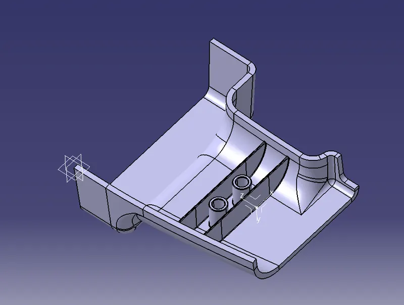
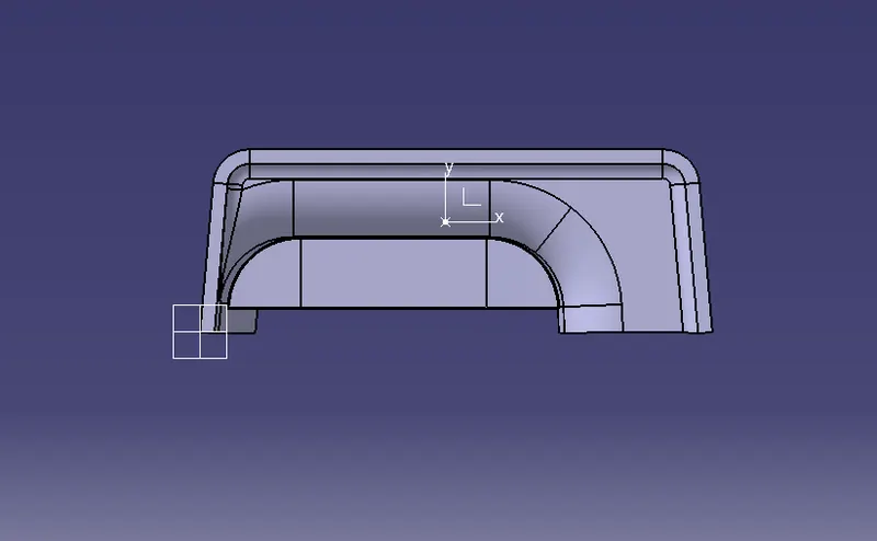
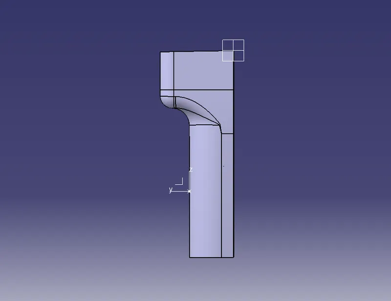
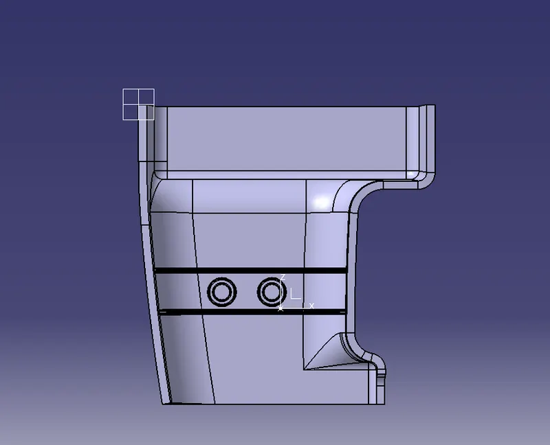
Draft analysis is done for the final part
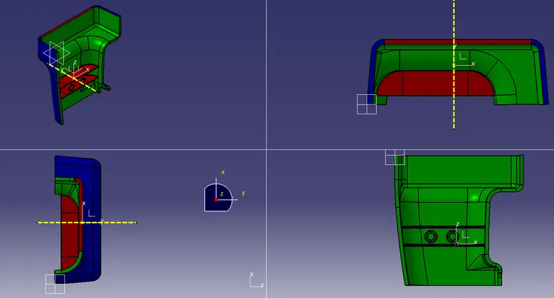
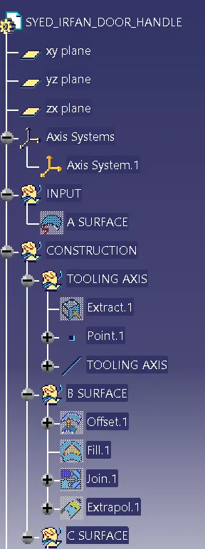
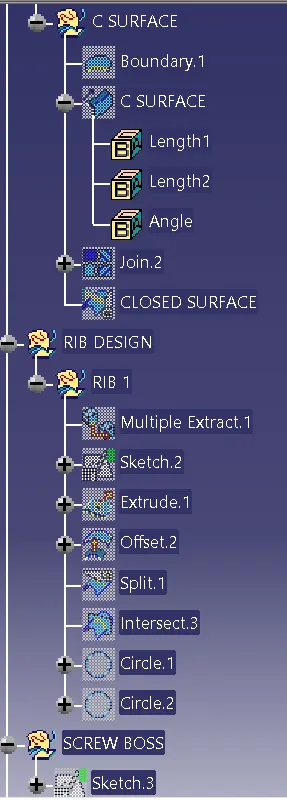
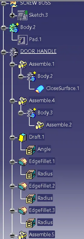
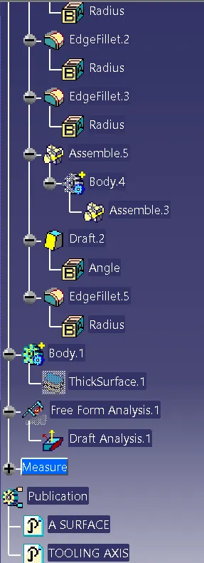
Tree structure of Geometrical set and Part body