FINAL INDEPENDENT PROJECT
Solidworks-Final Independent Project
TITLE:
DESIGN AND MODELLING OF THE LOCKHEED MARTIN C-130J SUPER HERCULES
ABSTRACT:
Any product developed in an industry comes out from the mind of a designer through the design,simulation, manufacturing and testing process. With the wide spread of popularity and versatility of CAD in various professional domains like product design, industrial design, etc. has become essential for a design engineer. It Being a design professional, I have always wanted to use Solidworks platform for completely designing and rendering my favorite aircraft, the C-130j-30. As an independent project to conclude my Solidworks training module, this design was the perfect fit. It presented me with an unique opportunity to implement the features I have learned and to add my own spin to it since the Project Brief offered me to prepare a design of my choosing with elements that I wanted to incorporate design approach. The following design methodology briefly explains the steps1 taken for completion of the design.
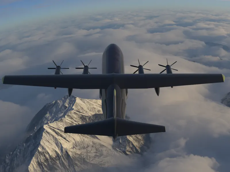
This report contains a detailed part modelling, assembly, final rendering of a custom-designed C-130J-30 in SQLIPWORKS as a CAD tool. Part modelling in general means creating a virtual prototype of each part. It can be used for various purposes. In part modelling, we first sketch the part/ component and create the 3D part using different features. Each part of the assembly is modelled separately and they are assembled together with the application of mates in assembly. Once the final assemble a model of the aircraft is ready, we can do rendering, for the project real view / realistic rending in done in Solidworks Visualise. A suitable environment, lighting and background setting is done for the rendering.
INDRODUCTION:
Designing of c-130j aircraft is to understand advanced surface modelling techniques in solidworks software. with the help of blue print of c130j we can create the 2d sketching to create surface and solid bodies. then the parts will assembled in assembly workbench and with with the help of solidworks visualize create a real view image.The C-130j-30 is a stretched/advanced version of the Hercules. The C-130 Hercules is the standard against which military transport aircraft are measured. Versatility, reliability, and ruggedness make it the military transport of choice for more than 60 nations on six continents. More than 2300 of these aircraft have been delivered by Lockheed Martin Aeronautics company since it entered production In 1956. The newest Hercules, the C-130j, has the same rugged good looks as its predecessors, but in fact, is a greatly improved aeroplane with the performance and capability to prove it. Compared to the earlier C-130E, the maximum speed is 21 percent higher, climb time is reduced by up to 50 percent, cruising altitude is up to 40 percent higher, and range is up to 40 percent longer.
OBJECTIVE:
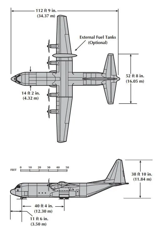
This objective of this project to design and modelling of a lockheed martin c-130j super hercules aircraft using solidworks software features and tools. this project designed with the help of blueprint and airfoil data base naca number of c-130j aircraft. and This project is to Understand,
- Blueprint setup
- Generate the airfoil
- 2d sketching
- 3d sketching
- surface modelling
- Design solid body
- Assembly
- Real view rendering
Blueprint
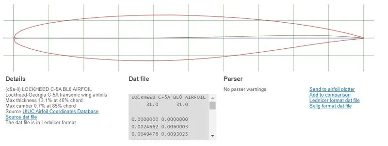
airfoil data base
SOFTWARE'S USED:
3D Modelling-SOLIDWORKS 2017.
Rendering- Solidworks visualize and Solidworks Photoview 360.
METHODOLOGY:

COMPONENTS OF C130J AIRCRAFT
They are,
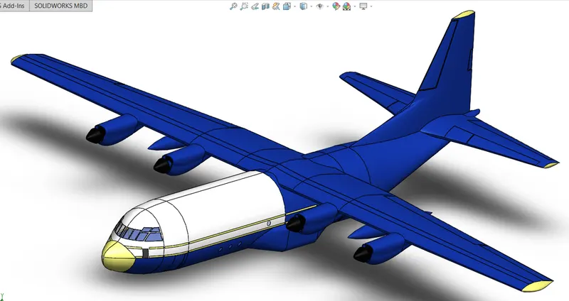
c130j cockpit and wings
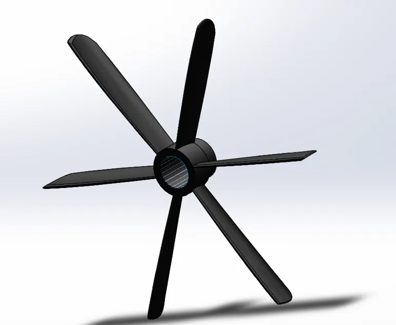
propller
DESCRIPITON:
Details of 3D modelling in solidworks
- Solid Modelling
Solid modeling is the most advanced method of geometric modeling in three dimensions. Solid modeling is the representation of the solid parts of the object on your computer. The typical geometric model is made up of wireframes that show the object in the form of wires. This wireframe structure can be two dimensional, two and a half dimensional or three dimensional. Providing surface representation to the wire three-dimensional views of geometric models makes the object appear solid.
- Surface Modelling
surface modelling to create complex shape of a feature on the external facets of an object. it develops an object by extending a surface over it and with the help of 3D curves that are produced by the designer. In other words, you are depicting the boundaries of the surface of an object.
Feature's Used:
- Sketch
2s sketch-Line,Circle,spline, conor Rectangle, 3 point arch, convert entities, mirror entities, linear sketch pattern, entities(move,copy, resize), offest entities, sketch picture, Blocks.
3d Sketch-Line,Circle,spline, conor Rectangle, 3 point arch, convert entities, mirror entities, linear sketch pattern.
- Surface Features
Swept Surface, Lofted Surface, Filled Surface, Offset Surface, Kint Surface, entend Surface, Extruded Surface, Trim Surface, Curve Through XYZ points.
- Solid Features
Extrude Boss/Base, Revolved Boss/Base, Lofted Boss/Base, Extruded Cut, Filet, Chamfer, Linear pattern. Circular pattern, Mirror, Shell, Plane, Split, Combine, Projected Curve.
- Appearance
An appearance defines the visual properties of a model, including color and texture. Appearances do not affect physical properties, which are defined by materials. Every material is assigned a default appearance that emulates the look of the material. Contents. Appearance Hierarchy.
Features Used to create blueprint setup
- Rename the plane
Top plane - Top plane of blueprint setup
Right plnae - midplane of blueprint setup
This project designed as following Features and tools.
Create Reference Geomentry/new plane
additon of sketch pictures to with respeted to each plane
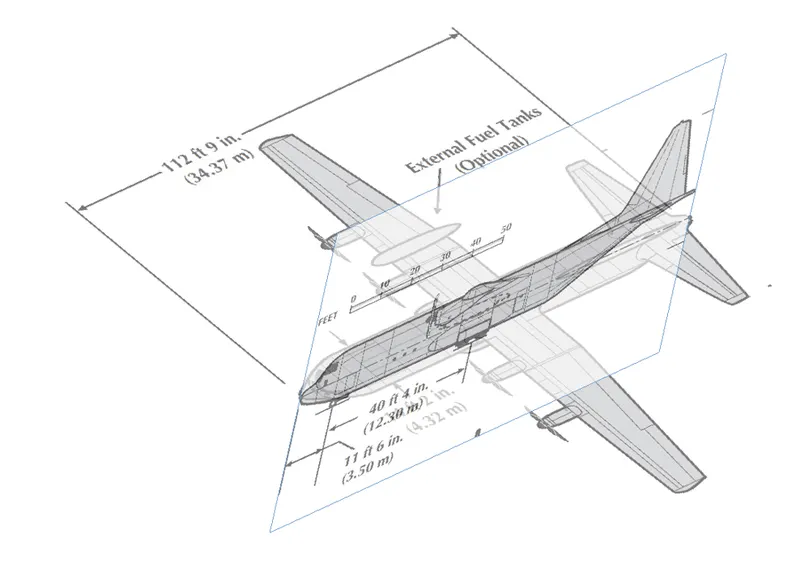
Fig: Blueprint setup for c130j aircraft.
Surface-loft: Used to construct a B-spline parametric surface that is transformed between section elements (lines, line strings, arcs, ellipses, complex chains, complex shapes, B-spline curves, or the edges of a surface).The loft feature is an important tool for (surface) modeling in SolidWorks. The loft feature creates a shape by making transitions between multiple profiles and guide curves. This tool is very valuable for modeling complex surfaces.
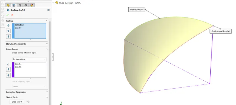
Fig: Loft surface using on curves.
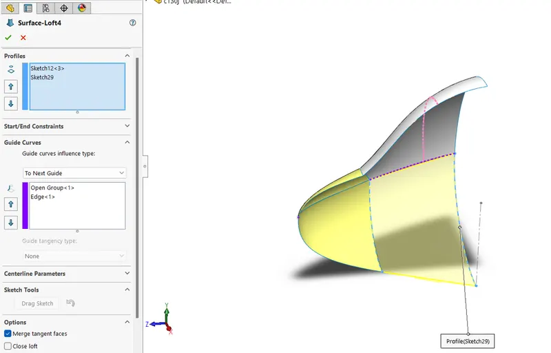
Fig: Loft surface using on curves.
Surface-Trim: Trim tool can use a surface in conjunction with additional surfaces, as mutual trim tools. Trim surface includes the following options: To trim a surface: Create two or more surfaces that intersect at one or more points, or create a surface that intersects with a plane or has a sketch on its face.
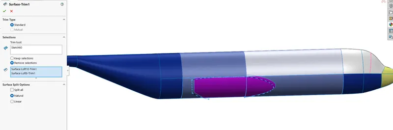
Fig: image shows uising surface-trim Feature.
Surface-loft: Used to construct a B-spline parametric surface that is transformed between section elements (lines, line strings, arcs, ellipses, complex chains, complex shapes, B-spline curves, or the edges of a surface).The loft feature is an important tool for (surface) modeling in SolidWorks. The loft feature creates a shape by making transitions between multiple profiles and guide curves. This tool is very valuable for modeling complex surfaces.
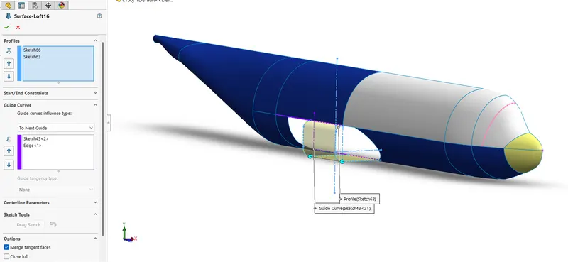
Fig: Loft surface using on curves.
Surface-Extend: You can extend a surface by selecting an edge, multiple edges, or a face.
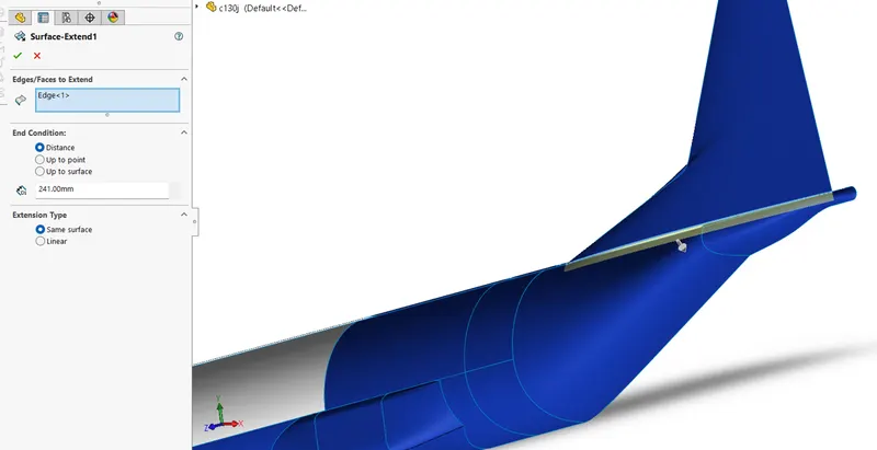
Fig: Surface extend using on surface
Airfoil: airfoil, also spelled Aerofoil, shaped surface, such as an airplane wing, tail, or propeller blade, that produces lift and drag when moved through the air. An airfoil produces a lifting force that acts at right angles to the airstream and a dragging force that acts in the same direction as the airstream.
To design airfoil we can use Curve Through XYZ points tool to instert curve with airfoil tool generater (airfoiltool generate with naca number of aircraft) and i maked it in to block
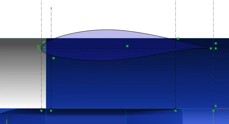
Fig: Shows inserting airfoil using block
Surface-Knit: Knit surfaces absorb the surface bodies you used to create them. Create a solid body when the knit surfaces form a closed volume, or leave as a surface body. Select Merge entities to merge faces with the same underlying geometry. with this feature we can use to control the gaps.
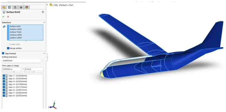
Fig: show using Kint surface and gaps control
Surface-extrude: You can create extruded surfaces from models that include 2D or 3D faces and knit the extruded surfaces to surrounding features.
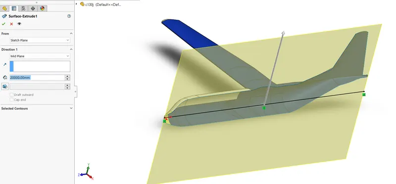
Fig: Using Surface Extrude Feature
Loft-base/boss:Sketch your profiles. A minimum of two are required but a higher number of profiles allows you to create more complex shapes.
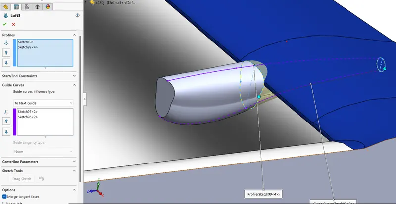
Fig: Using Surface Loft Feature
Cut-Extrude: Extruded cut feature removes material from the part. The End Condition, Draft, and Thin Feature options are same as described in Extruded Boss/Base.
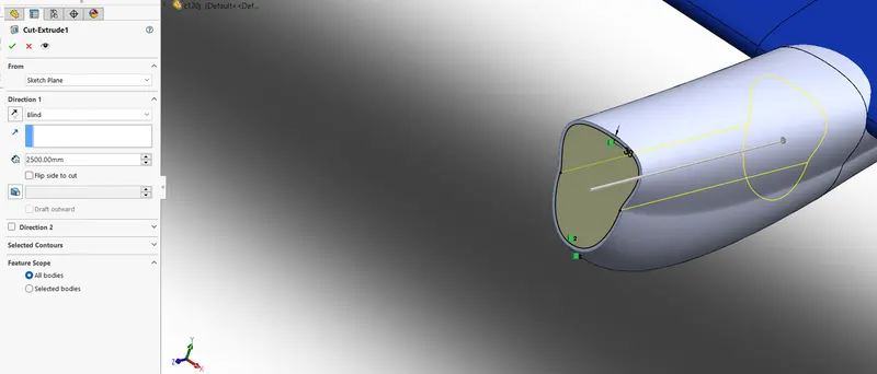
Fig: Using Cut-Extrude Feature
Fillet:Fillet/Round creates a rounded internal or external face on the part. You can fillet all edges of a face, selected sets of faces, selected edges, or edge loops.
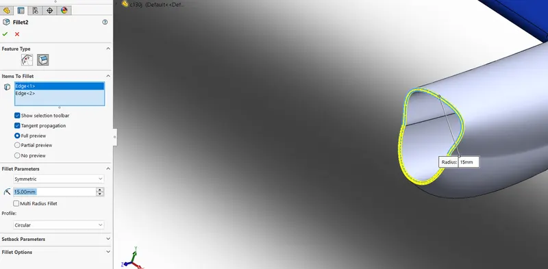
Fig: Using Fillet Feature
Boss-extrude: Extrude tool is used to extend a sketched profile in one or two directions as either a thin feature or a solid feature. An extrude operation can either add material to a part (in a base or boss) or remove material from a part.
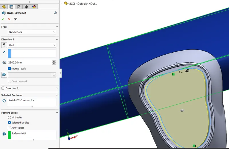
Fig: Using Boss-Extrude Feature
Fillet:Fillet/Round creates a rounded internal or external face on the part. You can fillet all edges of a face, selected sets of faces, selected edges, or edge loops.
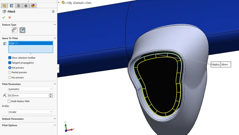
Fig: Using Fillet Feature
Boss-extrude: Extrude tool is used to extend a sketched profile in one or two directions as either a thin feature or a solid feature. An extrude operation can either add material to a part (in a base or boss) or remove material from a part.
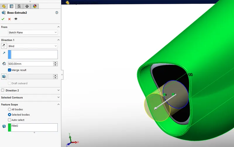
Fig: Using Boss Extrude Feature
Revolve:Revolves add or remove material by revolving one or more profiles around a centerline. You can create revolved boss/bases, revolved cuts, or revolved surfaces. The revolve feature can be a solid, a thin feature, or a surface.
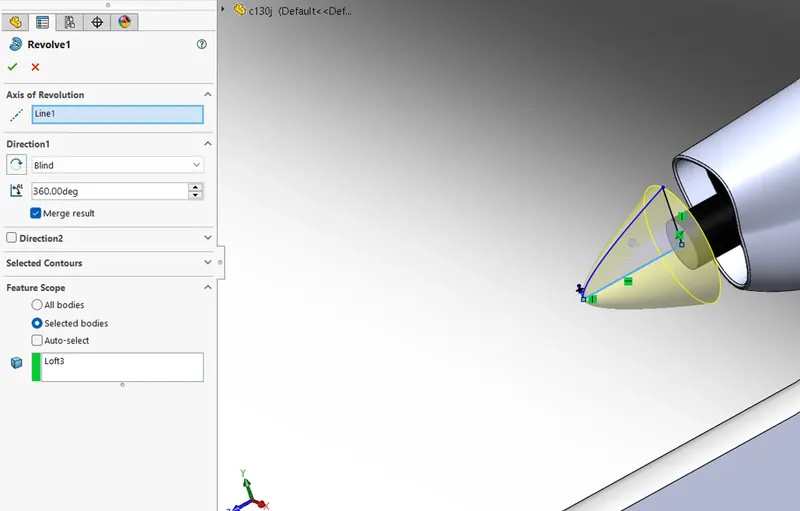
Fig: Using Revolve Feature
Combine: The Combine feature in SOLIDWORKS is a great tool used most often in surface modeling as it allows you to take molds of created parts for mold operations. It is also useful when creating negative spaces for a part to fit into to show where an item might reside in an assembly.
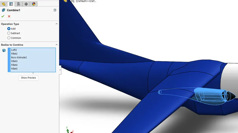
Fig: Using Combine Feature
Mirror: Select Mirror Entities to mirror pre-existing 2D sketch entities on a plane, and then select the entity about which to mirror. If you want to first select the entity about which to mirror, and then sketch the entities to mirror, select Dynamic Mirror Entities.
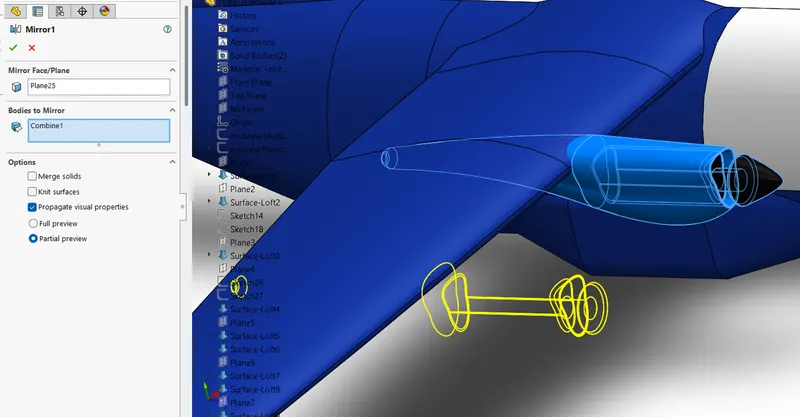
Fig: Using Linear pattern Feature
Revolve:Revolves add or remove material by revolving one or more profiles around a centerline. You can create revolved boss/bases, revolved cuts, or revolved surfaces. The revolve feature can be a solid, a thin feature, or a surface.
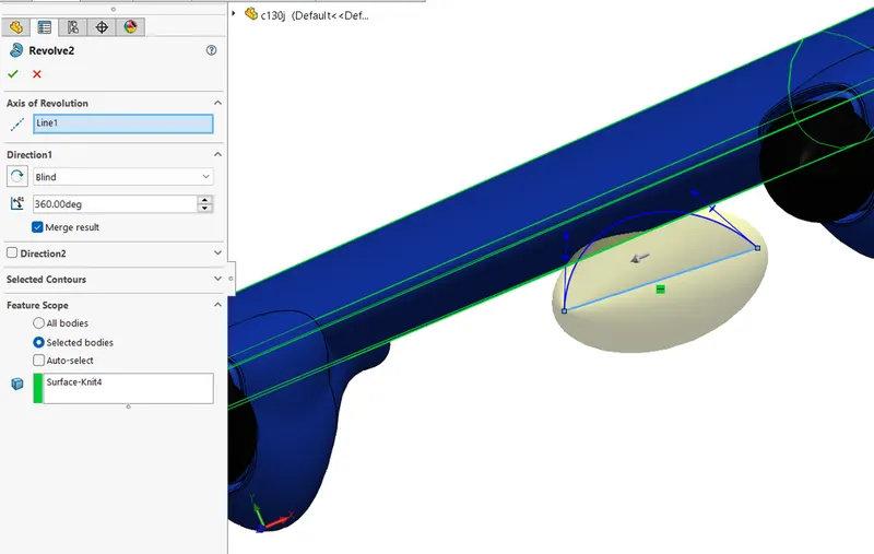
Fig: Using Revolve Feature
Loft: Loft-base/boss:Sketch your profiles. A minimum of two are required but a higher number of profiles allows you to create more complex shapes.
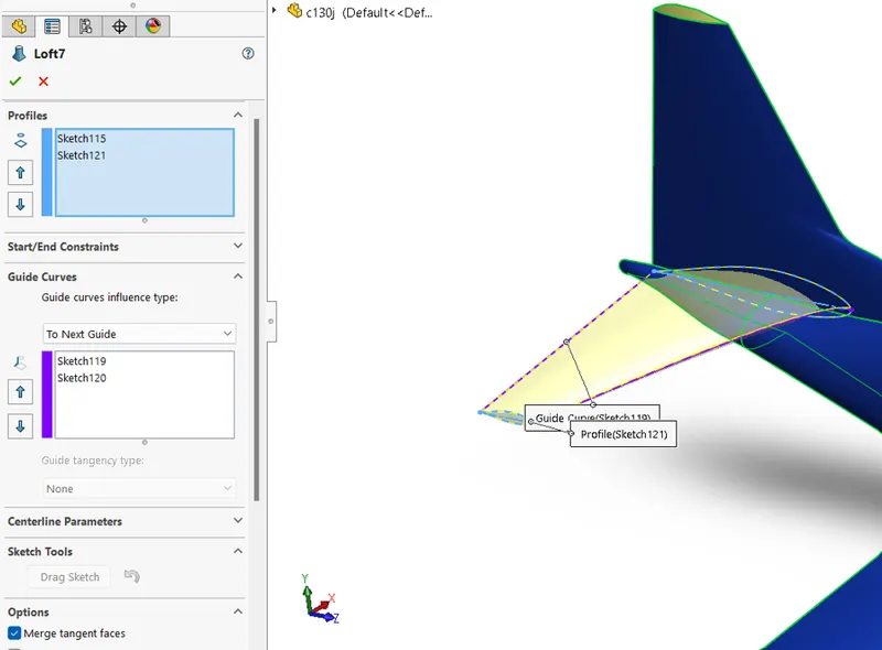
Fig: Using Loft Feature
Mirror: Select Mirror Entities to mirror pre-existing 2D sketch entities on a plane, and then select the entity about which to mirror. If you want to first select the entity about which to mirror, and then sketch the entities to mirror, select Dynamic Mirror Entities.
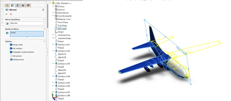
Fig: Using Mirror Feature
Cut-Extrude: Extruded cut feature removes material from the part. The End Condition, Draft, and Thin Feature options are same as described in Extruded Boss/Base.
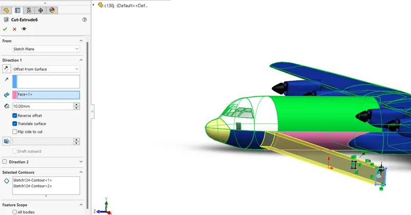
Fig: Using Cut-Extrude Feature
Offset Surface: The offset surface tool is useful way of creating a series of deposit or erosion contact surfaces from a reference mesh. The surface can be offset from the reference mesh by points or by a fixed distance, and additional options for offsetting to points can be adjusted once the surface has been created.
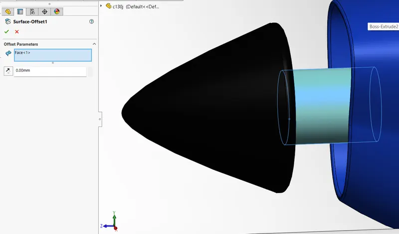
Fig: Uisng surface offset Feature
Loft: Loft-base/boss:Sketch your profiles. A minimum of two are required but a higher number of profiles allows you to create more complex shapes.
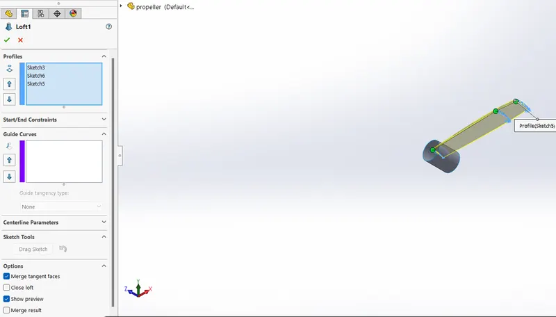
Fig: Using Surface Loft Feature
Loft: Loft-base/boss:Sketch your profiles. A minimum of two are required but a higher number of profiles allows you to create more complex shapes.
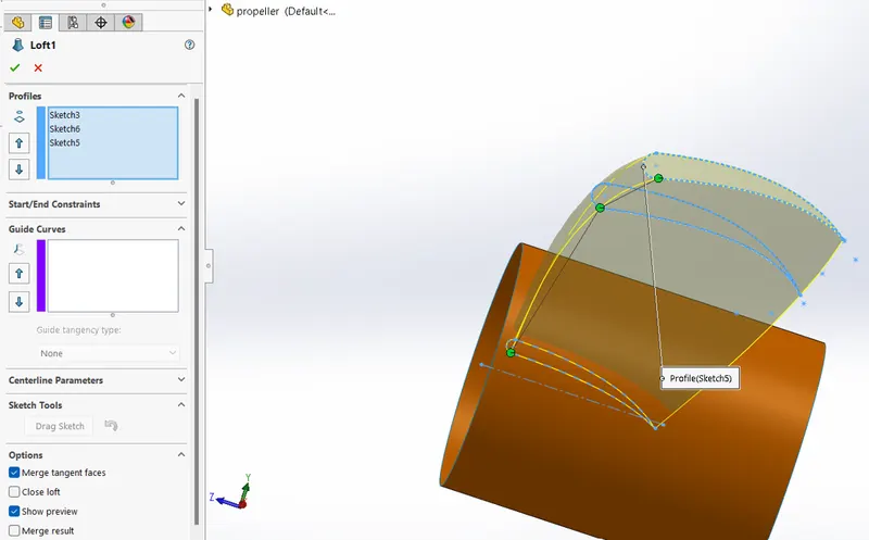
Fig: Using Surface Loft Feature
Split Tool: The Split Line. tool projects an entity (sketch, solid, surface, face, plane, or surface spline) to surfaces, or curved or planar faces. It divides a selected face into multiple separate faces. You can split curves on multiple bodies with one command.
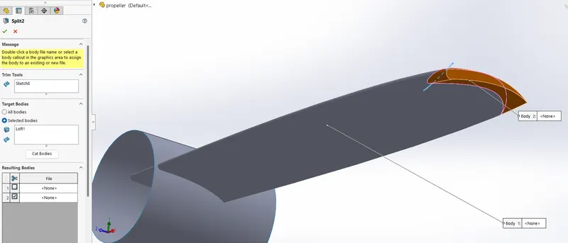
Fig: Using split tool
Revolve:Revolves add or remove material by revolving one or more profiles around a centerline. You can create revolved boss/bases, revolved cuts, or revolved surfaces. The revolve feature can be a solid, a thin feature, or a surface.
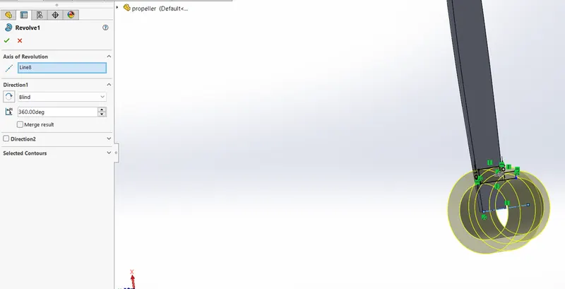
Fig: Using Revolve Feature
Circular pattern: Use circular patterns to create multiple instances of one or more features that you can space uniformly around an axis. Pattern instances inherit the feature color of the original feature when the: Pattern is based on one feature.
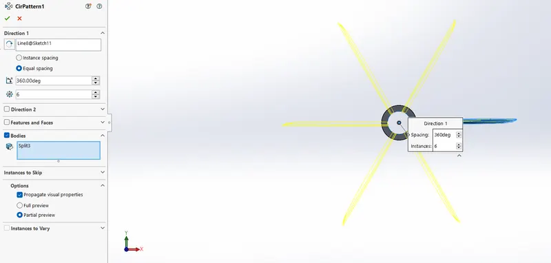
Fig: Using circular pattern Feature
ASSEMBLY OF C130J AIRCRAFT:
You can build complex assemblies consisting of many components, which can be parts or other assemblies, called subassemblies. For most operations, the behavior of components is the same for both types. Adding a component to an assembly creates a link between the assembly and the component.
An assembly opens with the insert components property managerb active. add the parts to the assembly. mainly insert all parts by using inset components feature.
Make sure every part has per axis and with using mate feature parts will be fixed.
Mate: Mates are constraints that hold components together in solidworks assemblies.
Images(front view, side view, top view, isometric view, camera view)
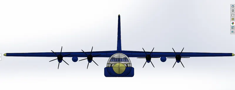
Fig: Front view of assmebly c130j aircraft.
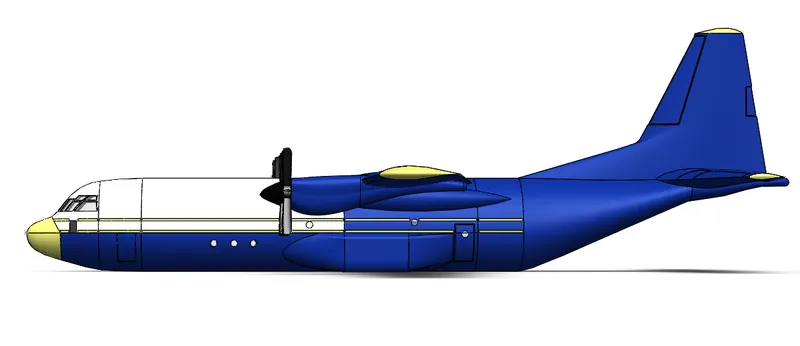
Fig: side view of assembly c130j aircraft.
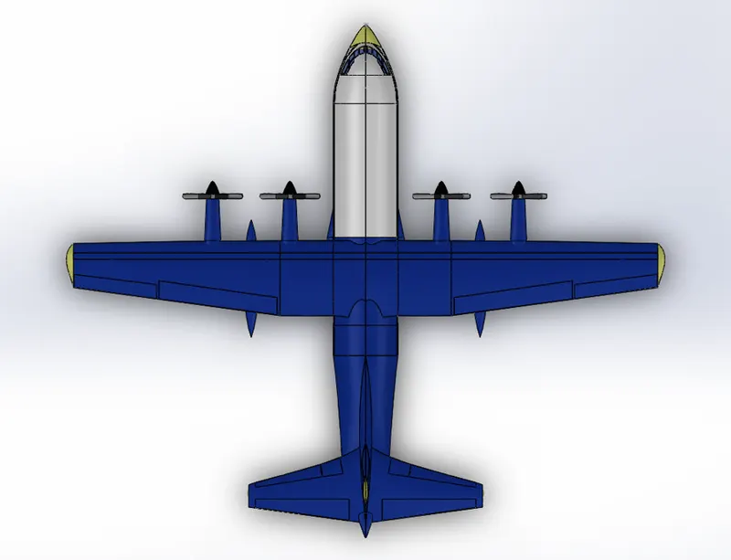
Fig: Top view of assemby c130j aircraft.
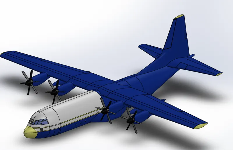
Fig: isomitric view of assembly c130j aircraft.
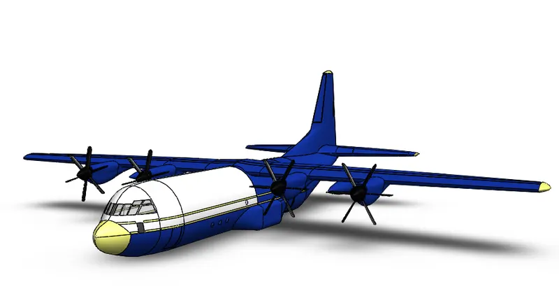
Fig: camera view of assembly c130j aircraft.
RENDERING OF C130J AIRCRAFT
Rendering is the process to make a real-time image.
Rendering considers the following features
- environment setup
- light settings
- camera setting
- colours and material settings
- scene composition
Setup is done by using solidworks photoview 360 with the above features
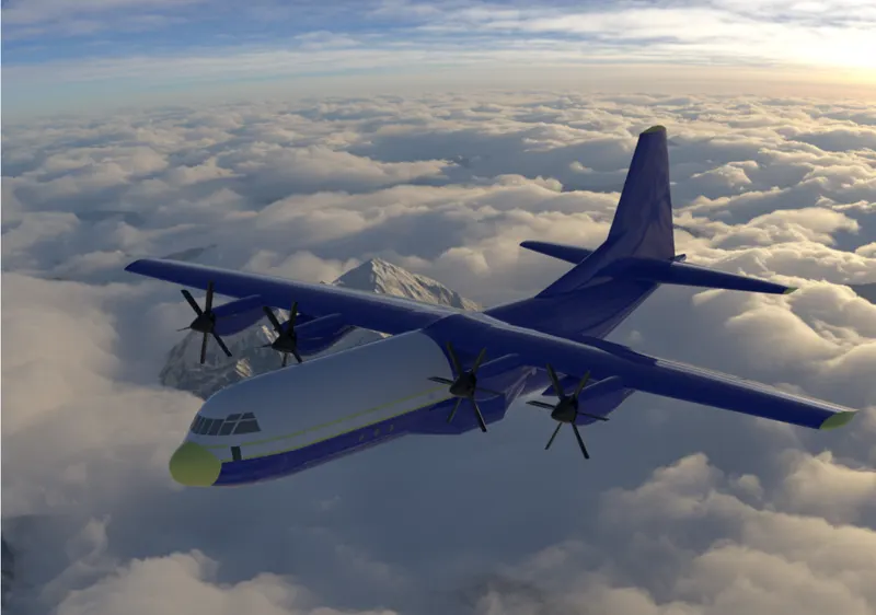
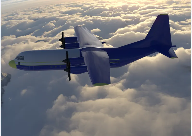
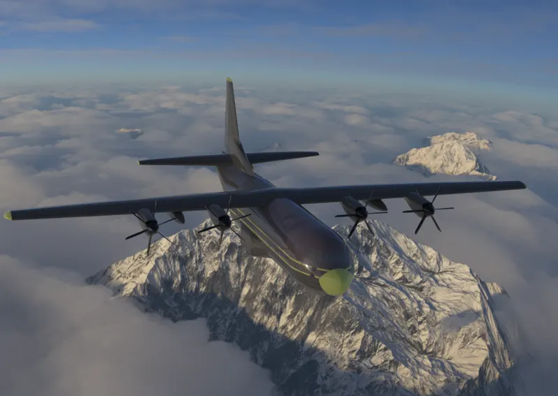
solidworks visualize software used to get a real-time image
RENDERING IMAGES:
CONCLUSION:
In this project the various parts of c130j aircraft was modeled with the differnt environments surface modeling. Solid modeling and assembly avaliable in the solidworks.
Assembly of c130j aircraft is rendered with photoview 360 and solidworks visualize to create a real view of the model with the environment.
This Project has helped to learn surface modelling and product design.
solidwork software user interface is easy to bulid the project.
REFERANCE:
https://www.lockheedmartin.com/content/dam/lockheed-martin/aero/documents/C-130J/C130JPocketGuide.Pdf