Week 9 - Attachment Feature Creation (Ribs & Screw Boss) - Challenge 1
AIM:
To Create the door handle with rib and screw boss plastic component with the help of class A and create Class B Surface & Class C Surface. At the end perform a close surface operation on the final close surface of the model.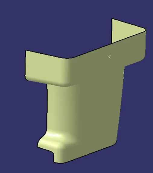
PROJECT DETAIL
Here the class A surface of the door coin holder was provided as in OEMs. we need to create class B & class C surfaces from class A. Then I created a solid body of 2.5 mm uniform thickness using class A, class B & class C surfaces. Finally, successfully performed the draft analysis of the component. The steps to be followed for the creation of this component are given below
DRAFT ANALYSIS
A draft is an angle at which the parts are tapered to allow them to release. As the part cools at a high temperature, it tends to shrink to the core side of the mold. The draft allows the parts to release easily from the mold without creating friction between the surface of the component and the core and cavity plates.
Draft analysis is performed based on color ranges identifying zones on the analyzed element where the deviation from the draft direction at any point, corresponds to specified values. The draft is required on all parts in the direction of mold movement to allow parts to release or eject properly.
Most applications require a minimum draft angle of around 5o to 1o, however, 3o draft angles are widely accepted for cost-saving purposes. 7o draft angles are given to textured surfaces like instrument panels. Due to their critical nature, the minimum possible draft angles are given to screw bosses, ribs, and stiffeners.
PROCEDURE:
- Verify Class A
- Tooling axis
- Draft analysis on Class A surface
- Creating class B surface
- Creating class C surface
- Joining class A and class C
- Final trim of class B with class A and class C
- Check the boundary for the final close surface
- Perform the closed surface operation on the final surface
- Conduct the draft analysis on the close body
- Publish the final tooling axis class A, B, and C surfaces, closed surface, part body, and final draft analysis
- Creation of rib and screw boss according to the rules.
- Conclusion
- CLASS A SURFACE:
In automotive plastic design, a class A surface is any set free from high efficiency and quality surfaces. Class A surfacing is done using a computer-aided industrial design application design engineers develop their design styling through the A-Surface software.
Design check on Class A Surface:
After receiving class a for the door handle check for the connectivity of the surface on it. If there is any disconnectivity, use joins operation, multiple extracts, multi-section surface, boundary operation, and disassemble. Perform the Join operation to join the disconnectivity of the surfaces and merging distance =0.003mm and once again check Class A surface for disconnectivity and proceed further for the tooling axis.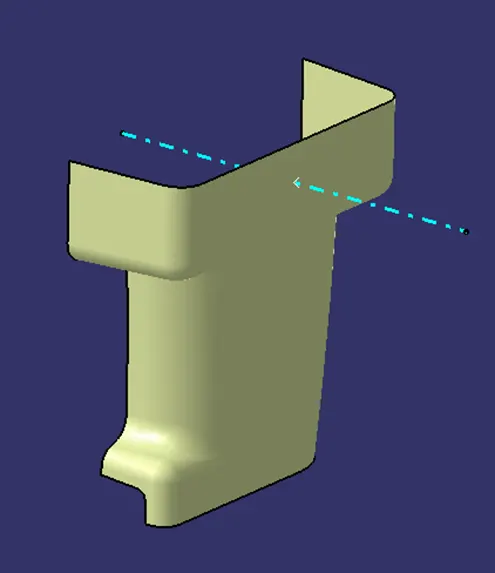
- TOOLING AXIS:
It is the direction in which the mold or core & cavity open. Part drafts are given along this axis.
Tooling operation:
To decide on the tooling axis, the component should be completely clearing the Tooling axis in the given specific direction.
The first one visually checks. We can check, which one is possible for Tooling Direction. We can check all x, y & z directions. If you have a hole, what will happen, you have a separate side core for a specific hole. In this draft analysis of door handle Z – direction the possible Tooling direction and tooling axis are created by bisecting method.
- DRAFT ANALYSIS:
Procedure:
- Change view mode
- Customize view parameters.
- Choose the material in the shading option.
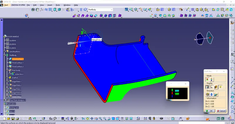
- Use the draft analysis option for class A surface and Tooling Axis.
- Go to INSERT – ANALYSIS – FEATURE DRAFT ANALYSIS.
- Place the compass on the tooling axis, lock the direction, and then left-click on the class A surface.
- Change the angle to minimum draft angle i.e, 3 degrees as per requirements.
- Find the color grading on the surface to avoid errors in the draft angle.
- CLASS B SURFACE:
Offset the class A surface to the thickness value [2.5mm] to get B Surface. It is a surface it gives thickness from Class A Surface, all the engineering features like screw boss, ribs, dog house, heat stacks, and other supporting features could be formed on the B Surface. In other words, Class B Surface know as Engineering Surface.
Surface operation:
- To create the thickness of the class A surface along with the following steps.
- To create the offset of 2.5mm surface area.
- Create the class B and extrapolate the class B surface
- Provide correct fillet values to avoid sharp edge
- CLASS C SURFACE:
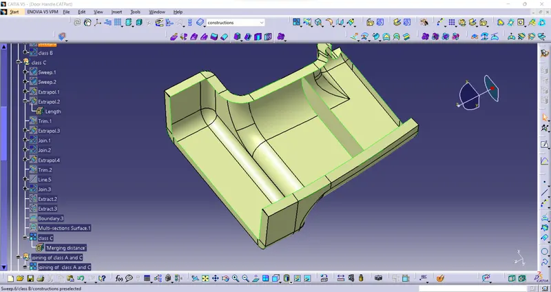
The purpose of Class C surfaces is to connect Class A surfaces & Class B surfaces. It gives the thickness of the model.
Surface operation:
- Perform sweep operation to create some thickness of profile with the draft angle of 3 degrees and draft direction is the tooling axis.
- Sweep class C surface more than the thickness and the extra surface can be trimmed.
- JOINING OF CLASS A and C: Perform the joining operation with 0.003 on the class A and C so that it can trim the class B surface to get the closed surface.
- TRIMMING OF CLASS A and C WITH CLASS B:
To get the closed surface as the thickness model we need to perform trim operation Class B with the final joining of Class A and C. before performing the trim operation check the intersection between the class B and joined surface of class A and C to know the disconnected points which are displayed in black.
8 . BOUNDARY OPERATION:
BY performing boundary operation we can able to find the open surface, if the final surface does not have any opening then boundary operation cant is performed thus it final surface is completely a closed surface.
- CREATING THE SOLID COMPONENT:
Step to create a solid component from a closed surface
Go to part modeling & click the close surface option it creates a complete model of the surface.
- DRAFT ANALYSIS OF THE SOLID COMPONENT :
Procedure:
- Change view mode
- Customize view parameters.
- Choose the material in the shading option.
- Use the draft analysis option for class A surface and Tooling Axis.
- Go to INSERT – ANALYSIS – FEATURE DRAFT ANALYSIS.
- Place the compass on the tooling axis, lock the direction, and then left-click on the class A surface.
- Change the angle to minimum draft angle i.e, 3 degrees as per requirements.
- Find the color grading on the surface to avoid errors in the draft angle.
RIB DESIGN:
To Create the rib for the Centre console coin holder.
INTRODUCTION:
Ribs provide a means to economical stiffness and strength in molded parts without increasing overall wall thickness.
They also facilitate Locating and arresting components of an assembly Providing alignment in mating parts Acting as stops or guides for mechanisms. This section deals with general guidelines for ribs and part design. Proper rib design involves five issues:
- Thickness
- Height
- Location
- Quantity
- Manufacturability
- Consider these carefully when designing ribs.
RIB THICKNESS:
Thick ribs often cause sink marks and in turn cosmetic problems on the opposite surface of the wall to which they are attached. The material, rib thickness, surface texture, color, proximity to a gate, and a variety of Processing conditions determine the severity of the sink.
A highly glossy, critical surface may require thinner ribs. Placing ribs opposite character marks or steps can hide rib read-through.
Thin-walled parts (<1.5mm) can often tolerate ribs that are thicker than the percentages in these guidelines.
On Parts with wall thicknesses that are 1.0 mm or less, the rib thickness should be equal to the wall thickness.
Rib thickness also directly affects moldability. Very thin ribs can be difficult to fill. Because of flow hesitation, thin ribs near the gate can sometimes be more difficult to fill than those further away.
RIB HEIGHT:
Rib height should not exceed 3 times the thickness of the primary wall. This height cap is recommended because if your ribs are too tall, they can break during use or eject from the mold. If damage occurs during the ejection of tall ribs, it is likely due to draft angles tapering them to slivers at their tips. Ideally, you want to keep your ribs as short as possible while still being functional.
- Rib height: 3*W (wall thickness)
- An additional problem that this combination of tall ribs and draft
- Causes is that the plastic may not be able to reach the tip of the rib.
- This can cause voids if the plastic can not flow into the very tip of the rib.
- Deep ribs can also be expensive to the tool. To avoid these problems, you can use several short ribs in place of one tall rib.
RIB WIDTH:
Thick ribs can result in huge problems on your part. If a rib is too thick, the point where it attaches to the primary wall or boss will be thickened as well. This can easily cause sink marks, warp, and voids where there is this excess material. In particular, sinks are visible indicators of bad design, which will affect the appearance of your finished part. If serve enough, sinks and voids can reduce the strength of a part as they become concentrated centers of stress. To prevent
- 5 and 0.75 times the primary wall thickness.
- Rib width: 0.5 – 0.75*W (wall thickness)
- Top rib thickness should be a minimum of 0.75mm
RIB SPACING:
- Increase the number of ribs rather than height to increase stiffness. Ribs should be spaced a minimum of two times the nominal wall thickness apart from one another.
- Rib spacing: minimum 2 *W (wall thickness)
- RIB DRAFT:
- A minimum 1 – degree draft will ensure that they release from the tool during molding.
RIB RADII OR FILLET:
- Radii at feature intersections should be a minimum of 0.25 of nominal wall thickness to increase rib strength.
- Rib radii or fillet: 0.25W (wall thickness)
RIB CORING:
- Core thick ribs from the back or below to create a blank area and thinner rib walls. This will help mitigate cosmetic sinks.
- Design rules for ribs in class A surface
- Draft – 0.5 degrees per side minimum
- Thickness – typically 40% wall thickness
- Height <or= 5 x wall thickness
- Spacing – 3:1 – steel height/width ratio maximum
- Minimum thickness at tip - 0.75mm
- Radii – 0.25mm maximum
- Ribs on the opposite side of the wall should be offset
- Ribs should be connected to other structural features where possible.
Guidelines for Bosses:
- Draft - 0.5 degrees on the walls of boss
- Thickness - Typically 40%* of the nominal wall at the base.
- Height to Diameter Ratio - 3:1
- Radii - 0.25mm maximum radii.
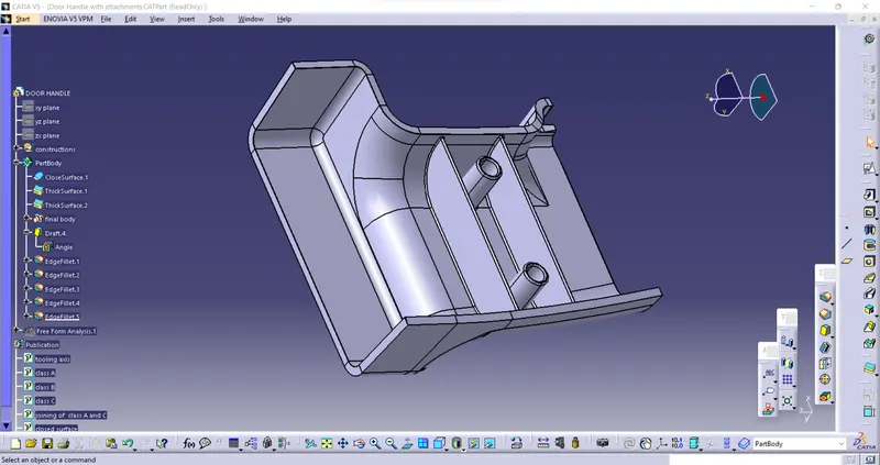
Final body with attachment:
CONCLUSION:
Obtained door handle with rib and screw boss the solid component from the class A surface by following the procedure