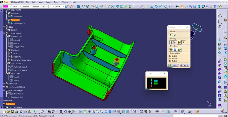
Week 9 - Attachment Feature Creation (Ribs & Screw Boss) - Challenge 1
AIM
Create the rib for the Drill Handle considering the design rules.
Create the Screw boss for the Drill Handle considering the design rules.
THEORY
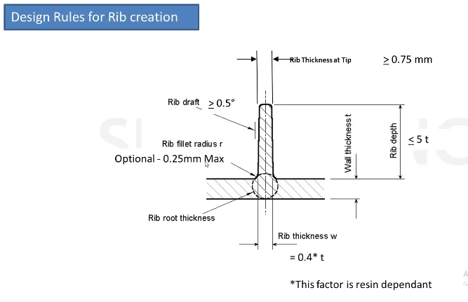
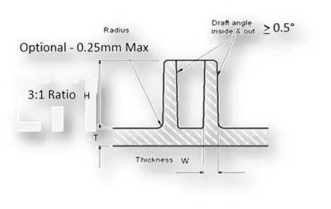
General Guidelines for Bosses:
- Draft - 0.5 degrees on the walls of boss
- Thickness - Typically 40%* of the nominal wall at the base.
- Height to Diameter Ratio - 3:1
- Radii - 0.25mm maximum radii.
PROCEDURE
CREATING TOOLING AXIS
Extracting base surface of class A surface using extract tool.
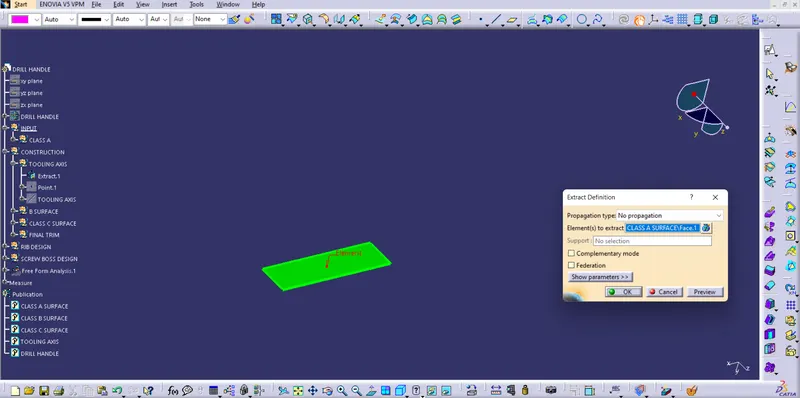
Creating a point on the center of extracted surface using point tool.
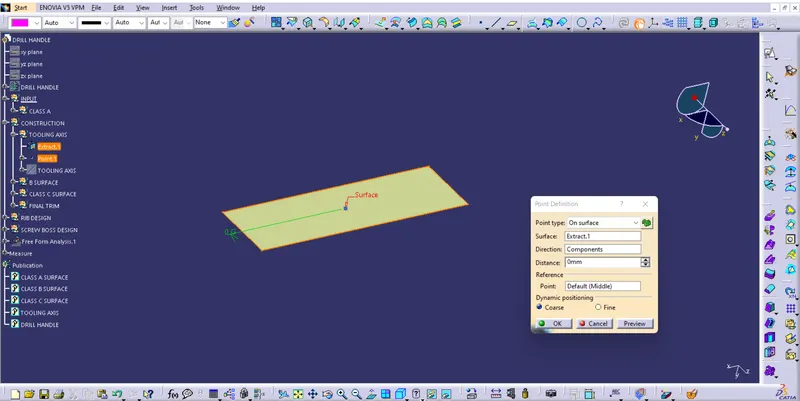
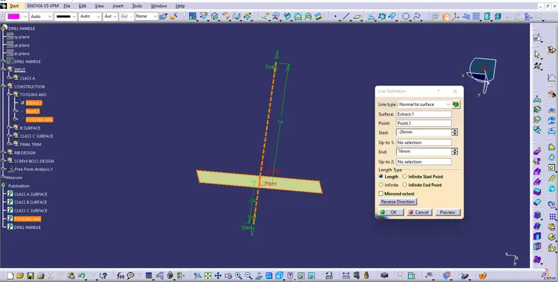
Tooling axis is created perpenticular to the surface line tool.
DRAFT ANALYSIS ON CLASS A SURFACE
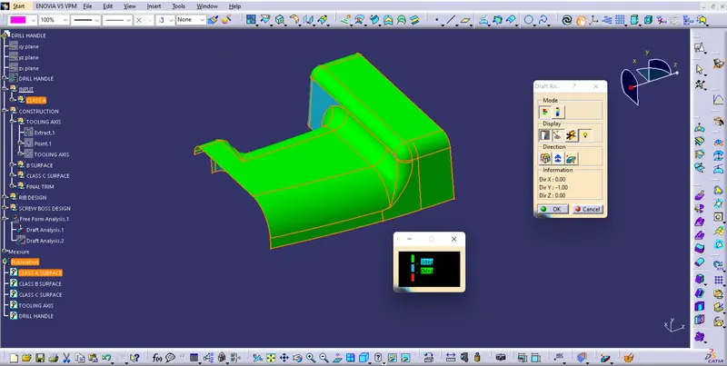
To perform draft analysis on the model:- Go to menu bar > select insert > Analysis > Feature Draft Analysis. To give the draft direction, use the compass and align Z-axis of it with the tooling axis. Once it properly aligned, lock the draft direction. A red point shown in the screen, select Base Bracket and it will show us the current of the model. Then go to display tab on draft analysis and select show Colour scale option and it will show the draft value. Set the Draft value to 3 deg under the colour scale variant and press ok.
CLASS A SURFACE
CLASS B SURFACE CREATION
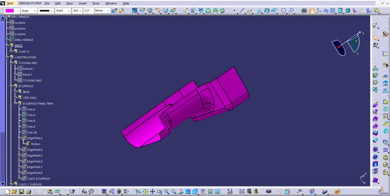
Class B surface is created by extracting the Class A surface, untrim the extracted surface then expolated the untrim surface after that the surface are offset to the distance 2.5 mm . After the this the trimmed with respect to class A surface and applying fillet to B surface.
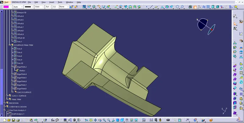
CLASS C SURFACE CREATION
Multiple extract the edges of class A surface.
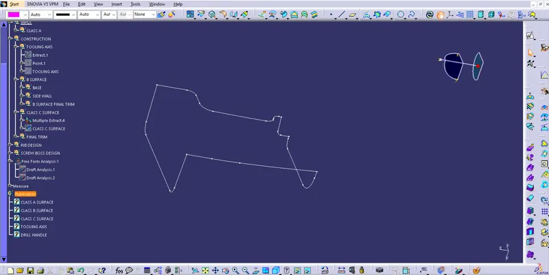
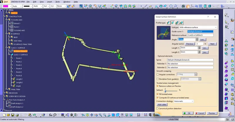
Extracted edges are sweeped using sweep tool with reference surface at an angle of 90 degree. The Class C surface is created
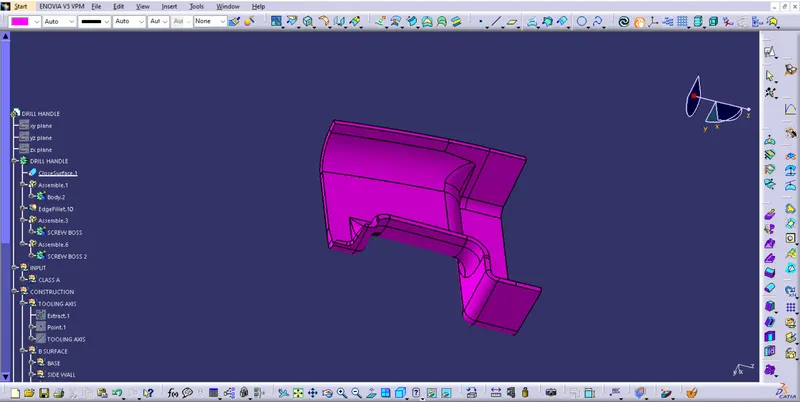
Trim the Class A,Class B and class C surface together to get final surface. Using close surface tool the final body is created.
RIB DESIGN
first we need to extract the base surface . Then create a point on the center of the base surface using point tool. A plane is created in that point parallel to ZX plane, A sketch is drawn as representing rib extrude the sketch to the required height and thicken it. Applydraft to the thicken face. Last split it with extracted surface then assembling it to the part body and edge fillets are applied.
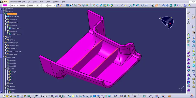
SCREW BOSS DESIGN
Creating sketch for screw boss pad it to the required height then draft the outer surface.
VIWES
ISOMETRIC VIEW

FRONT VIEW
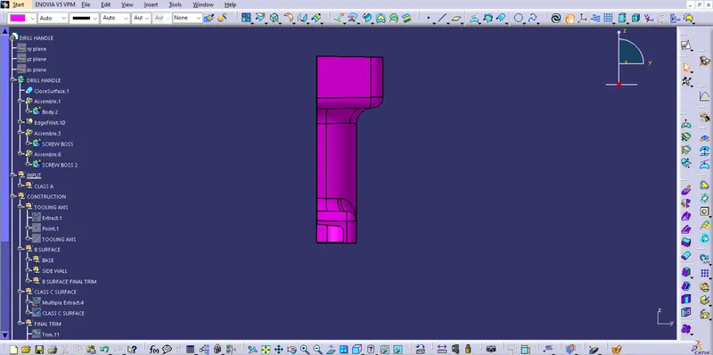
SIDE VIEW
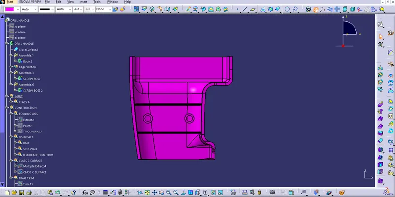
TOP VIEW
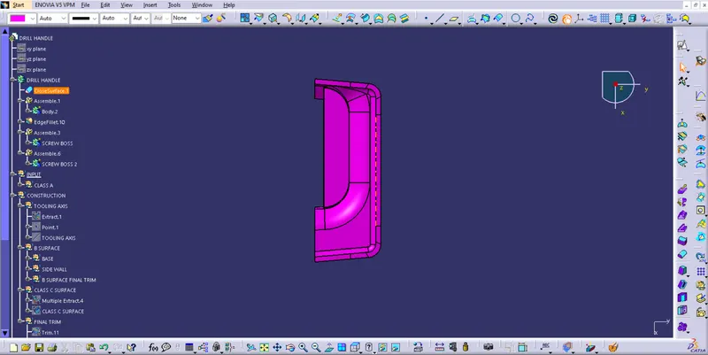
DRAFT ANALYSIS ON FINAL BODY
To perform draft analysis on the model:- Go to menu bar > select insert > Analysis > Feature Draft Analysis. To give the draft direction, use the compass and align Z-axis of it with the tooling axis. Once it properly aligned, lock the draft direction. A red point shown in the screen, select Base Bracket and it will show us the current of the model. Then go to display tab on draft analysis and select show Colour scale option and it will show the draft value. Set the Draft value to 3 deg under the colour scale variant and press ok.