Week 9 - Attachment Feature Creation (Ribs & Screw Boss) - Challenge 1
TOOLING AXIS & DRAFT ANALYSIS
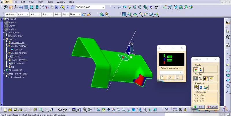
- After obersing the A surface, due to the presence of flat surfaces, a dummy tooling axis in the y direction was taken.
- When checked for draft, it did not satisfy the requirements.
- Then bisecting method was implemented and analysis was carried out. Even that did not suffice.
- Since it is not an option to edit the A surface, I took the initial dummy axis in the Y direction to be the main tooling axis.
Tooling Axis by Bisecting Method
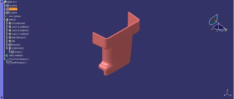
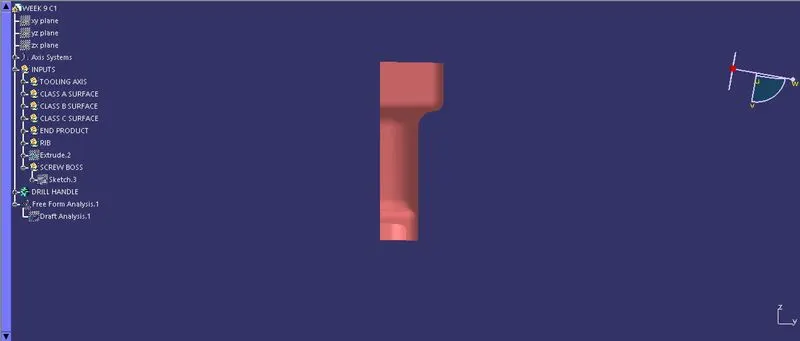
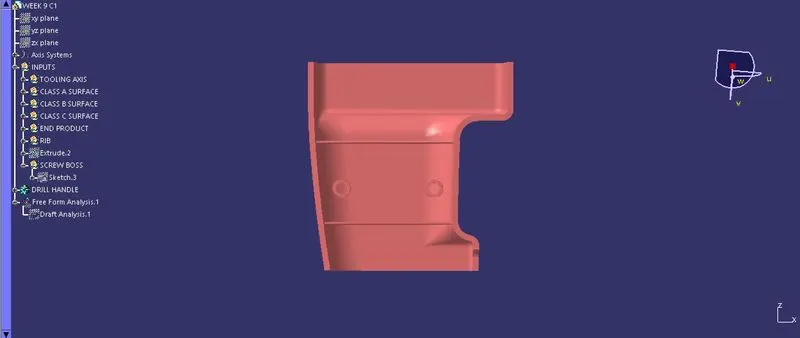
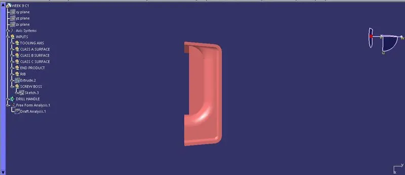
3D PART MODELS