Week 8 - Challenge 4 - Bumper
TOOLING AXIS
- First a point was created on the surface where it would be feasible to get the intersection of critical elements in both direction.
- An axis system was created at the point and intersections were taken along 2 mutually perpendicular planes.
- The lines from the intersections were projected and bisected to get tooling axis in that direction.
- The same was repeated for the other plane and another tooling axis was formed.
- Both these axis were then bisected to get another axis.
- Even at this stage some small strips did not satisfy the 3 degree draft requirement.
- Then compass in the draft analysis was placed along the created axis and was tilted to cover all the missed areas.
- The Position of the compass was locked and a new axis along this compass direction was created. This was the actual Tooling Axis.
DRAFT ANALYSIS CLASS A SURFACE
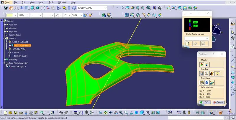
- In this challenge draft analysis was carried out multiple times for the purpose of checking and confirming the tooling axis.
- After multiple trial and errors, the tooling axis for which draft requirements almost satisfied was created.
- Then draft analysis itself was used to find actual tooling axis.
- The compass was placed along the closest axis and tilted to get the required response in terms of color code.
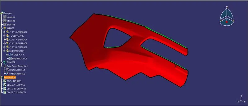
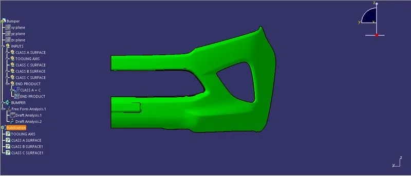
- The alignment of the compass in which the class A surface showed color code green was locked and taken to create the actual tooling axis.
DRAFT ANALYSIS END PRODUCT
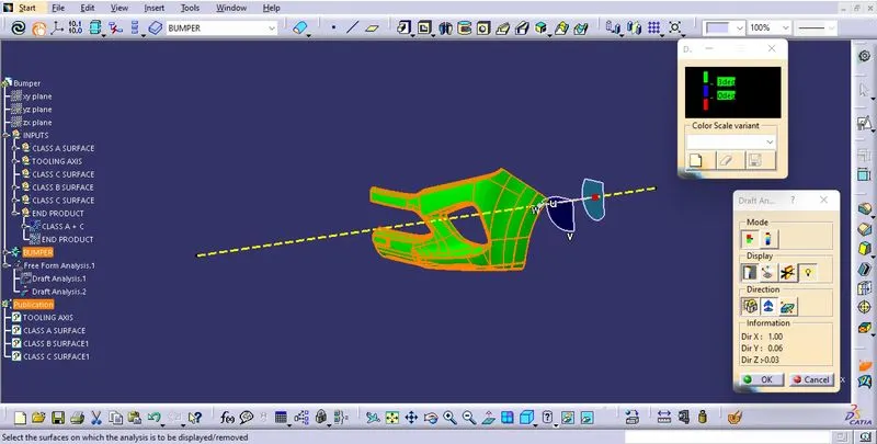
- On completion, the end product was analysed in the same manner.
- The compass was moved to align with the tooling axis and was fixed in position.
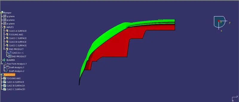
- The color code option was enabled and on clicking the end product, the surfaces having angles greater than 3 were highlighted in green and those having negative angles were highlighted in red.
- The running point analyser was also used to know the angle of draft.
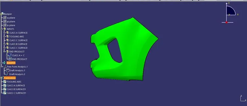
3D PART MODEL