Week 8 - Challenge 3 - Coin Holder Design
TOOLING AXIS
- After analysing the class A surface, due to the presence of the large cavity,it was understood that it woud be better to place the tooling axis with reference to the cavity.
- An axis system was placed in the middle of the cavity and was used to intersect the A surface in 2 mutually perpendicular planes.
- The inclined surfaces were projected in to lines and these lines were bisected to form 2 tooling axis respectively.
- The 2 tooling axes thus formed were further bisected to form the actual tooling axis.
DRAFT ANALYSIS CLASS A SURFACE
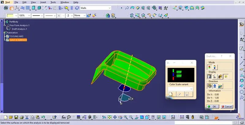
- After preparing the tooling axis, the A surface was analysed for draft.
- The compass was moved to align with the tooling axis.
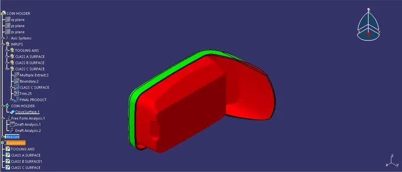
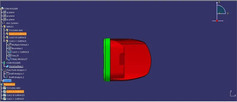
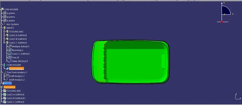
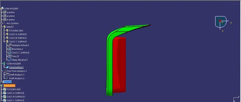
- The color code option was enabled and on clicking the surface, the surfaces having angles greater than 3 were highlighted in green.
- The running point analyser were used to check the draft angle values.
DRAFT ANALYSIS END PRODUCT
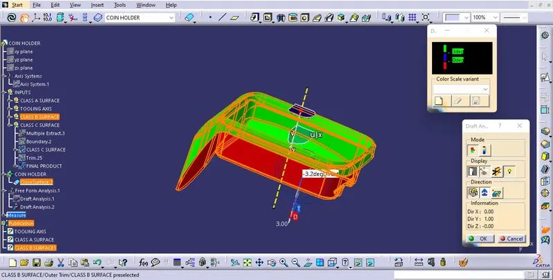
- On completion, the end product was analysed in the same manner.
- The compass was moved to align with the tooling axis.
- The color code option was enabled and on clicking the end product, the surfaces having angles greater than 3 were highlighted in green and those having negative angles were highlighted in red.
- The running point analyser was used to know the angle of draft.
3D PART MODELS