Week 8 - Challenge 2 - Switch Bezel Design
TOOLING AXIS
- A point was created on the base from which two planes perpendicuar to x and y axes were created.
- The A surface was then intersected by the plane parallel to the y dierction
- The two inclined lines were taken and bisected along the first point to create the tooling axis in y direction.
- Then the lines intersected by the other plane was used to create one line and another line was created manually with an angle such that the inclined surface had a draft of minimum 3 degree.
- These 2 lines then were bisected to create the tooling axis in x direction.
- Further these 2 tooling axes in x and y directions were bisected to get the actual tooling axis.
DRAFT ANALYSIS CLASS A
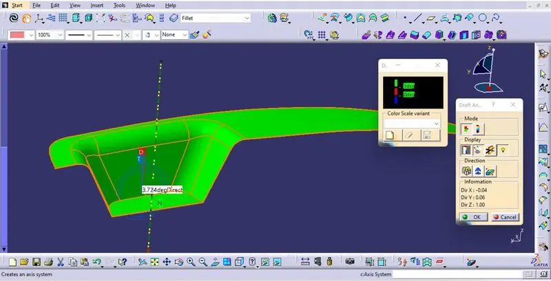
- Initially the Class A surface was analysed.
- The compass was moved to coincide with the tooling axis and then fixed it.
- Clicking on the surface and a color code was provided in which green implied draft angle was satisfied.
- The requirement was changed to 3 degrees.
- The tooling axis in x direction was adjusted to create the main tooling axis to fit the analysis.
DRAFT ANALYSIS FINAL PRODUCT
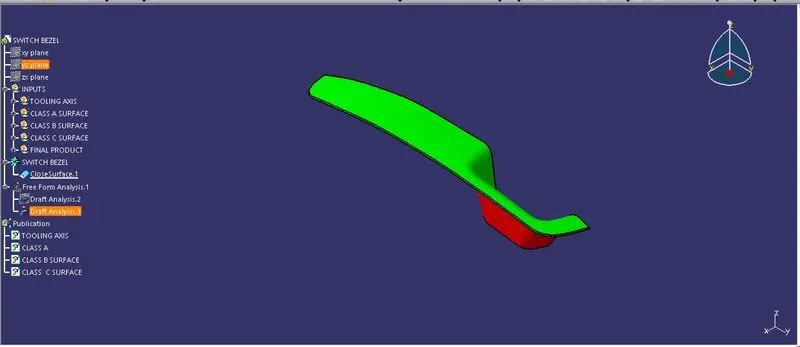
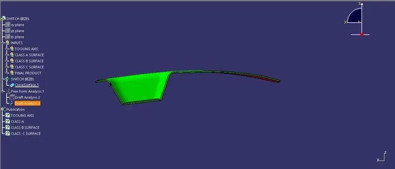
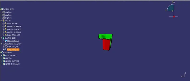
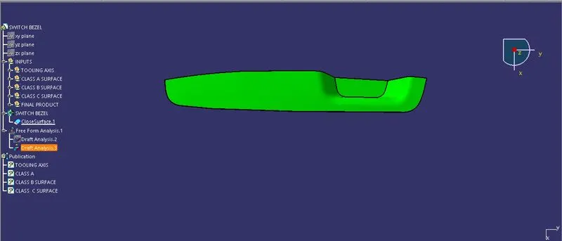
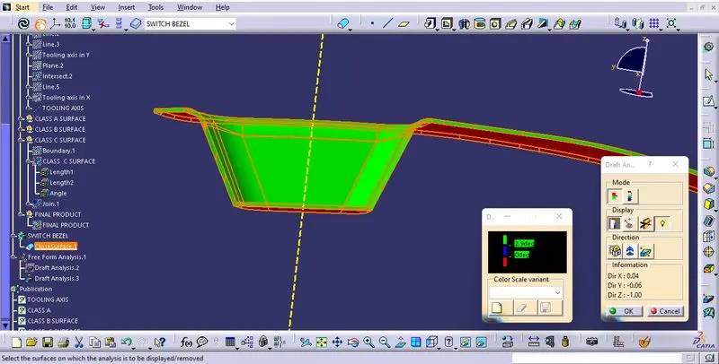
- After the final product was created, draft analysis was carried out again.
- The compass was again aligned with the main tooling axis and color code was taken.
- Since the class c surface was not at the 3 degree mark and varied between 2.9 and 3, the required angle was reduced to 2.9 degrees.
3D PART MODEL