Week 9 - Attachment Feature Creation (Ribs & Screw Boss) - Challenge 1
Aim:
To Create a DRILL HANDLE attach with B side features Ribs & screw
boss plastic component design throught the given CAT Part file from Class A surface To
make a Class B & Class C Surface and final component.
Used via
Catia V5 software- tools used given below,
Point through on the center of the surface
Axis creation
Line in point direction
Bisecting line
Intersection
Tool Axis
Draft Analysis in Free from Analysis
Untrim
Boundry
fill surface
Extruded surface Closed Surface
Thicken surface
Pad
Draft
Fillet
Tooling Axis creation:
It is defined as the direction in which the mold/core and cavity open. Then resultant tooling
axis is created using the bisecting method.
Selection of the direction of the tooling axis depends on the ease at which components ca
be easily ejected.
By analyzing the component the most easily ejectable direction is somewhere close to the
Z direction,(might be inclined to it) so we have made a sketch on the YZ plane of the Axis
System) to create a bisecting line considering the 2 faces which might be difficult to be
tooled.
Taking the Thickness of the component to be 2.5 mm
CLASS A
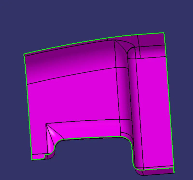
DRAFT ANALYSIS
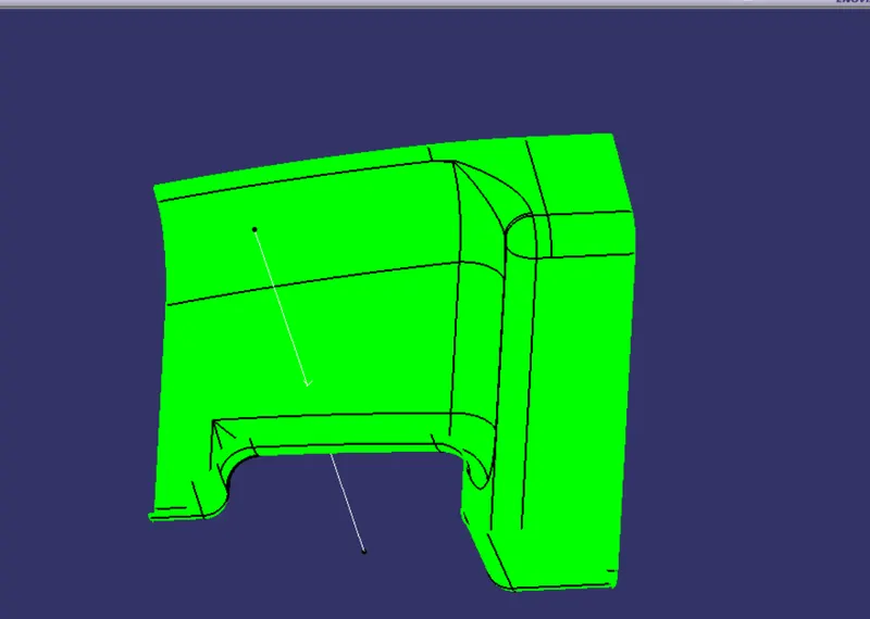
TOOLING AXIS
While creating the tooling axis we need to find the better view of the body will appear totall body
So we need to check each and every suface to get better and good tooling axis
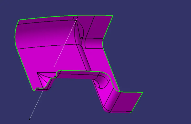
CLASS B
class B is offset from the class A the offset range is 2.5mm
In class B only we need to focus the each and every tool to find better way to get result out
After creating the offset we can see some patches when we offset the class A
Now we need to fill the patches through the help of procedure like
1.Extract the flat surface which we need
2.Now extrapolate the extracted surface
3.After extrapolating the surfaces we need to trim
4. Finally we want to trim the unwanted portion
This is the procedure where we use for every complex operations
After filling the patches we need to join the each and every patch and we need to complete the B surface
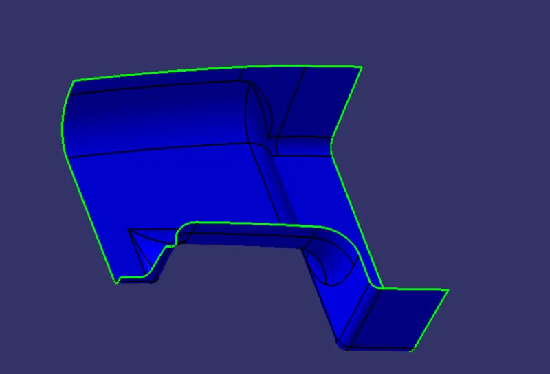
Class C:
Creation of class c is from class A to class C
We need to give extrapolate the class A to form class C
The above fig shows the Class C
For this out put we need to perform the various tools to get the exact output
In the creation of class c also we need to extrapolate some edges and we need to trim to get good output
After creation of class C we need to trim the 2 bodies such as class a &c class b
After triming we got an closed surface
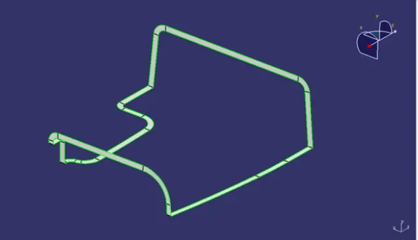
To find the body wheather it is closed surface or not we need to check with the help of boundary operation, if there is a any open surface we need to work on that to get closed body.
This way we can find the Closed body
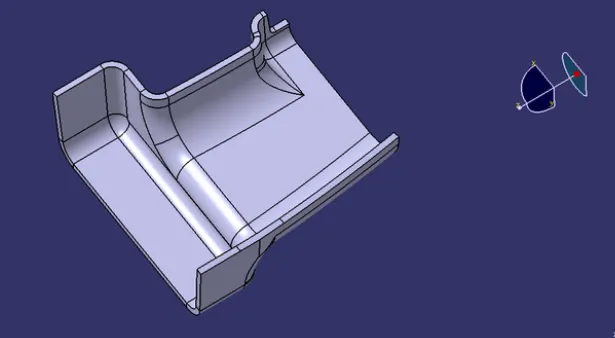
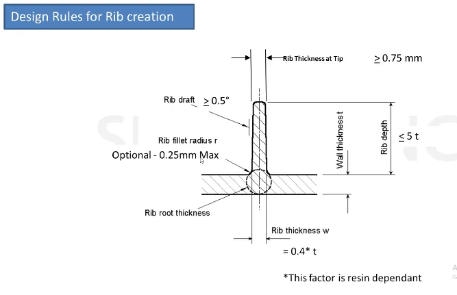
Here we need to perform the RIBS on the closed body
First we need to extract one surface and we need to do sketch on that extracted surface
We must use the design procedure to make the RIBS in a exact manner.
After drawing the sketch we need to extract the sketch
Now we need to use intersection to find the part which we created wheather it is good or not.
Now we need to insert the body and use Thicken Command.
Finally we need to add to the main part.
This is the process where we use to perform the Ribs.
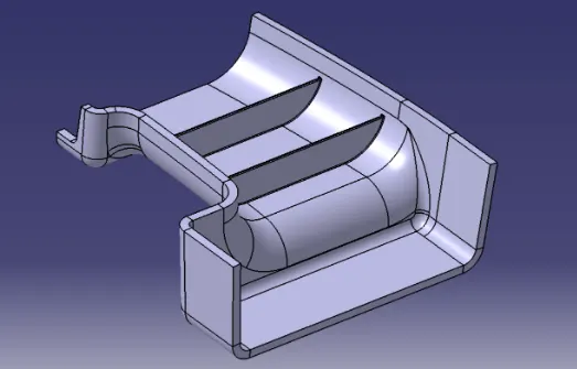
SCREW BOSS:
General Guidelines for Bosses:
- Draft - 0.5 degrees on the walls of boss
- Thickness - Typically 40%* of the nominal wall at the base.
- Height to Diameter Ratio - 3:1
- Radii - 0.25mm maximum radii.
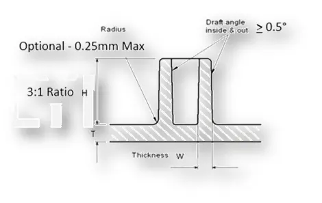
For creating a screw boss we need to check the circle diameter inner and outer circle
Now we need to use the positioned sketch to draw the circle we need to completely constrain the drawing.
Now we need to insert the Body and we need to pad the sketch
Now create another screw boss or Translate the body
To translating the body first insert the body and from the 1st body copy the sketch and paste in the another body
Now paste the body by using paste special inn this select the result link where it will copy the entire body
Now use draft and fillet command
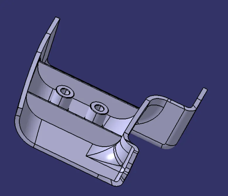
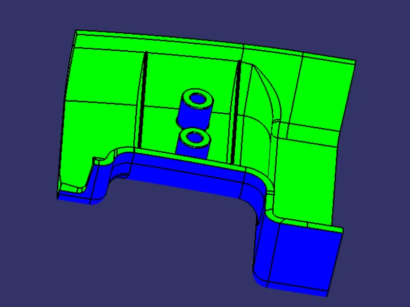
Finally we need to perfor the Draft Analysis for the closedbody surface.
VIEWS OF THE BODY
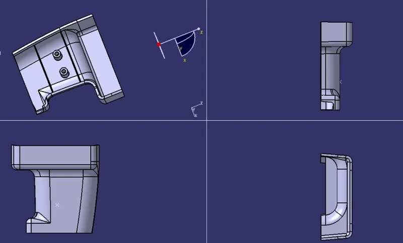
The views will define the which position and which face
So by viewing the we can easily understand the diagram
The views will understand easily when we see the body
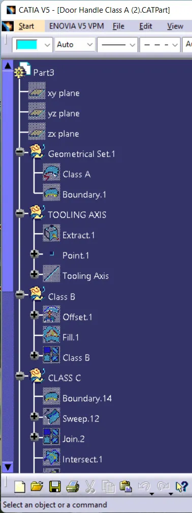
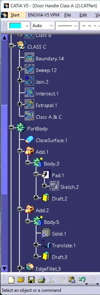
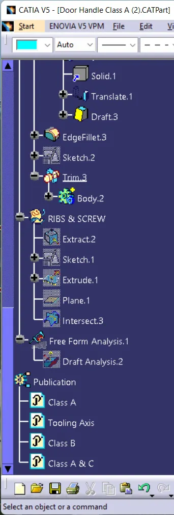
Geometrical Tree