Week 9 - Attachment Feature Creation (Ribs & Screw Boss) - Challenge 1
Attachment Feature Creation (Ribs & Screw Boss)
AIM:
- To Create the Door Handle Component from the given Class-A surface.
- To Create the tooling axis for the given Class-A Surface meeting the requirements of the draft angle.
- To Attach B side Features in the component.
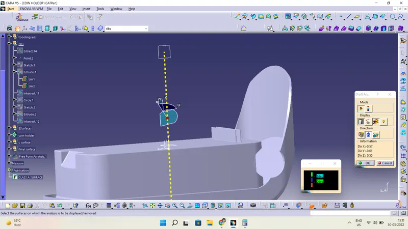
- To perform the Draft analysis on the model.
TOOLS USED:
- Boundary
- Join
- Multiple extract
- Bisecting line
- Trim
- Surface offset
- Draft analysis
- Intersect
- Surface sweep
- Close body surface
DESCRIPTION:
1. CREATING TOOLING AXIS -
The Tooling Direction is basically the direction that the mold pulls a part. The mold is built in two separate pieces, basically. You have a Cavity side and you have the Core side. The Core pulls apart from the Cavity and that's the Dye line or the Tooling Direction.
- Open the given CAT part file.
- Check for gaps between surfaces for that click on join and then preview.
- If theres any gap between the surfaces join them with a maximum tolerance of 0.003 mm.
- Extract the boundary and dissemble the boundary.
- Find the correct tooling axis where the material don't interfere with the tooling axis and all the elements can be created.
- Create an axis system using at the centre of the switch Bezel.
- Intersect the yz plane with respect to the class A surface.
- Hide the class A surface and create point to point lines on the suspected drafts.
- Create bisecting line with the two lines and point to create a tooling axis.
- BISECTING LINES were used to get the exact medium from the two sides so that maximum positive draft angle can be achieved
- The tooling axis is created for the component by bisecting two axis from x and y planes.
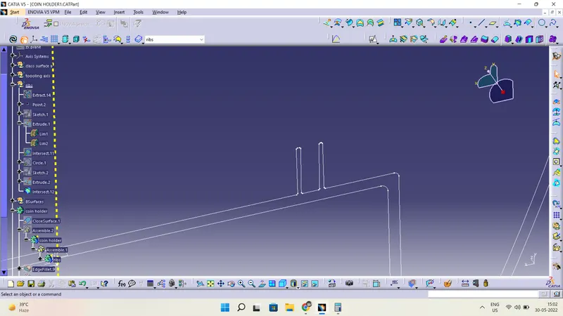
Ribs Design
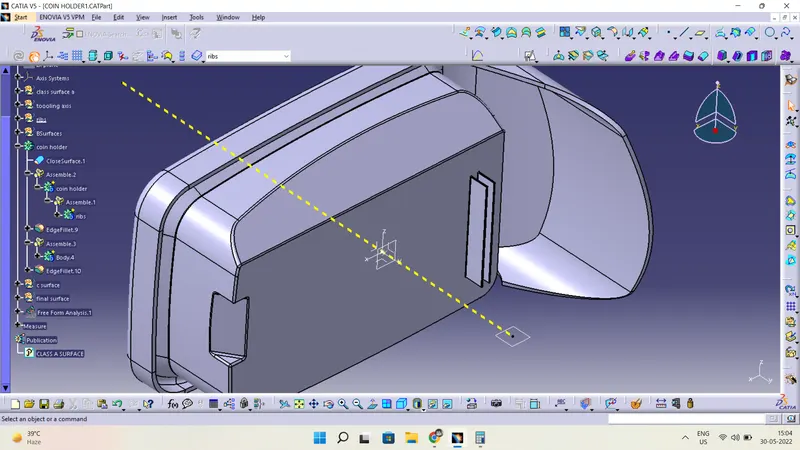
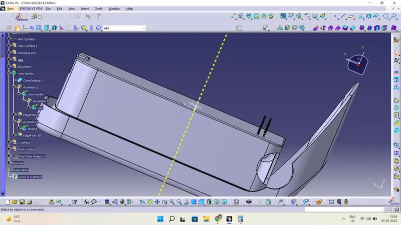
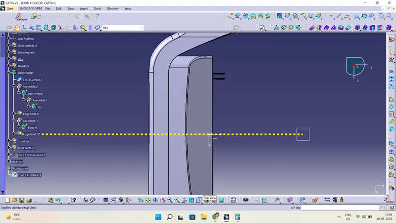
Intersection
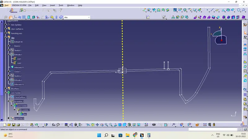
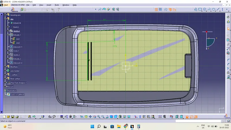
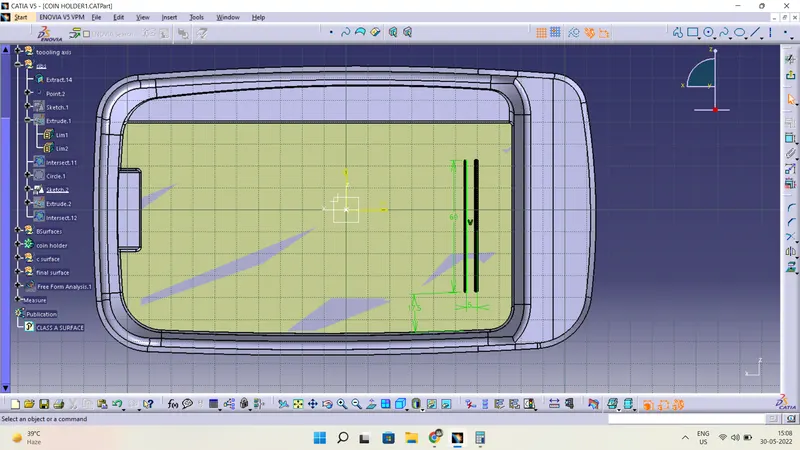
Ribs Sketching
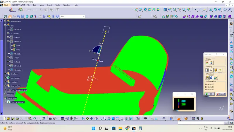
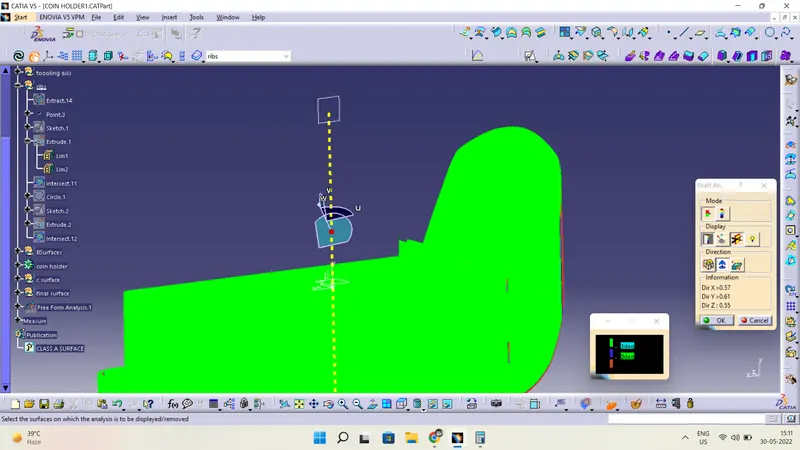
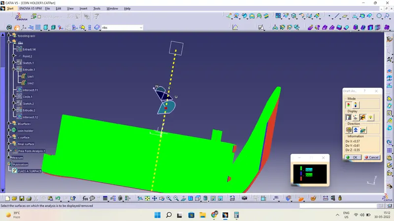
Draft Analysis
CONCLUSION:
The Tooling axis and the SolidCAT part with B Side Features is created from the given Class A Surface and Draft Analysis is Performed.