Attachment Feature Creation (Ribs & Screw Boss)
OBJECTIVE
Converting the given CLASS A surface into closed body and make Screw boss and rib on body and perform draft analysis
PROCEDURE
Given step file is convert into CAT and given bumper model taken as CLASS A SURFACE
CLASS A SURFACE
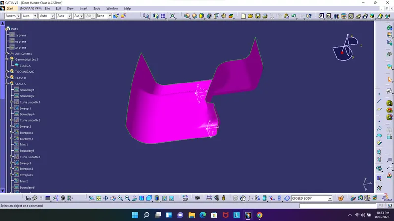
Check for gaps between surfaces for that click on join and then preview. If theres any gap between the surfaces join them with a maximum tolerance of 0.003 mm.
TOOLING AXIS
Normal tooling axis does not working here
- First intersect the surface and extract 2 surfaces
- Then make 2 line on the surface and bisect line using the point
- now we get the dummy tooling axis, again intersect with the YZ plane extract a line
- make a 5 degree line with respect to the line make second dummy axis
- now bisect two lines to get the TOOLING AXIS
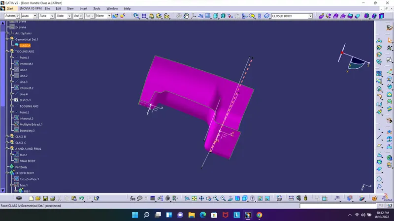
DRAFT ANALYSIS
The Draft Analysis command enables you to detect if the part you drafted will be easily removed. This type of analysis is performed based on color ranges identifying zones on the analyzed element where the deviation from the draft direction at any point, corresponds to specified values.
- The draft analysis is done by clicking feature drafat analysis or go to TOOLS>ANALYSIS>DRAFT ANALYSIS
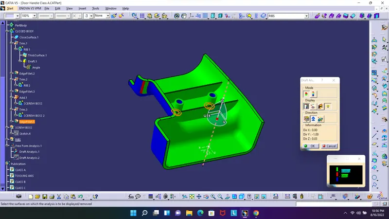
- on the bar select the compass and place it on the tooling axis and lock the compass and click on the body
- As u can see the body comes in GREEN in colour that ie angles are under 3 degree and ready to draft
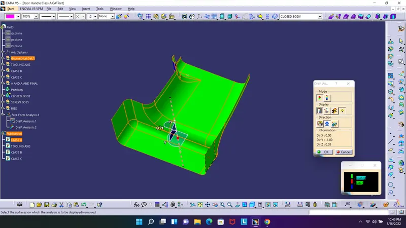
(some of area does not pass draft analysis)
CLASS B CREATION
we can easily off set the CLASS A by 2.5 mm and create class B ssurface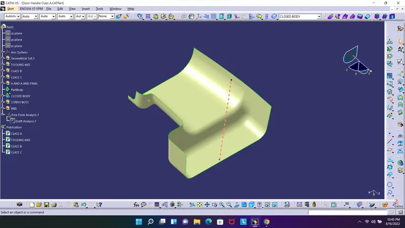
CLASS C CREATION
- Extract the boundary from the class A surface using boundary command.
- Use sweep command > choose profile type line > subtype as with draft direction > choose guide curve and draft direction > draft angle as 3 degree > preview.
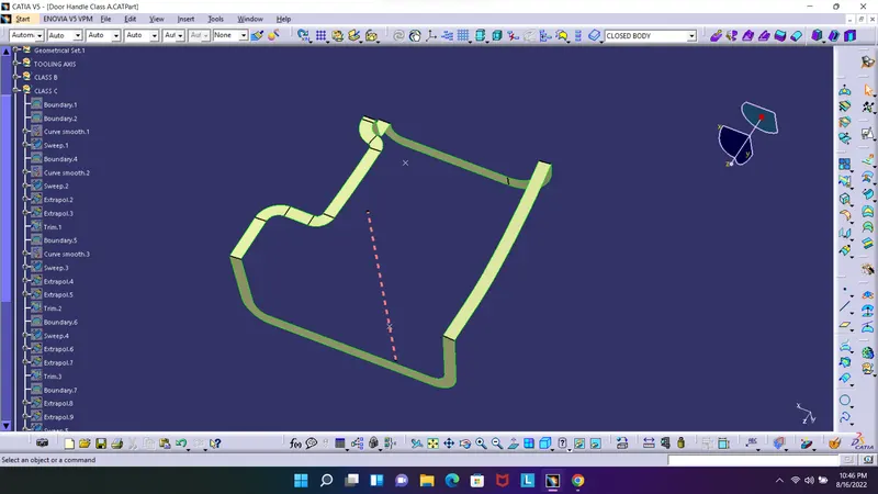
- After class C creation Join Class A and Class C and trim it between class B to get Final body
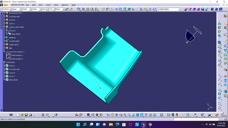
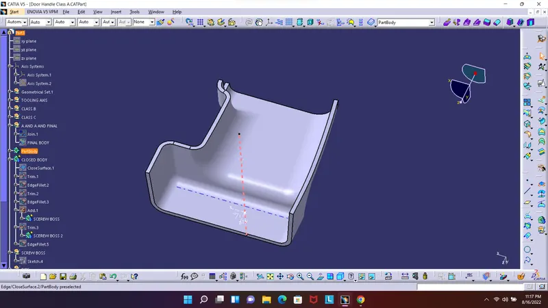
- By moving to part body and using closed surface tool make a part body
RIBS
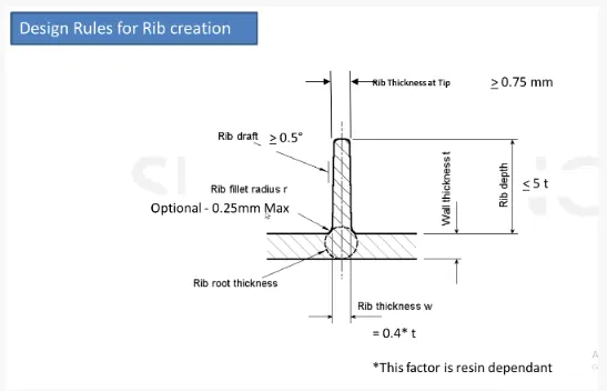
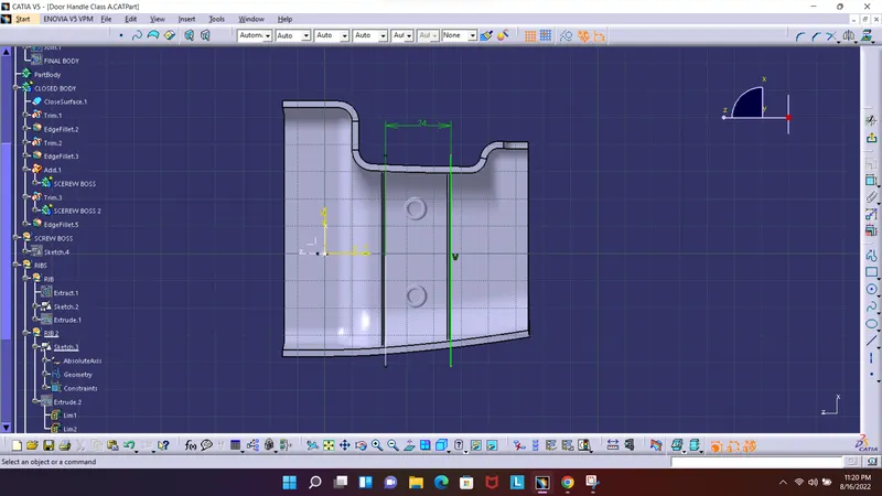
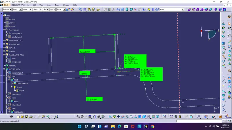
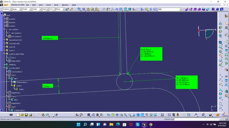
- Create 2 line on closed body with sketch (since length between body cannot take 5 mm due to consider screw boss length taken as 24 mm)

SCREW BOSS
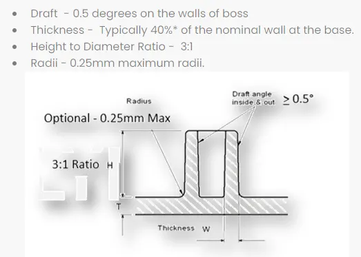
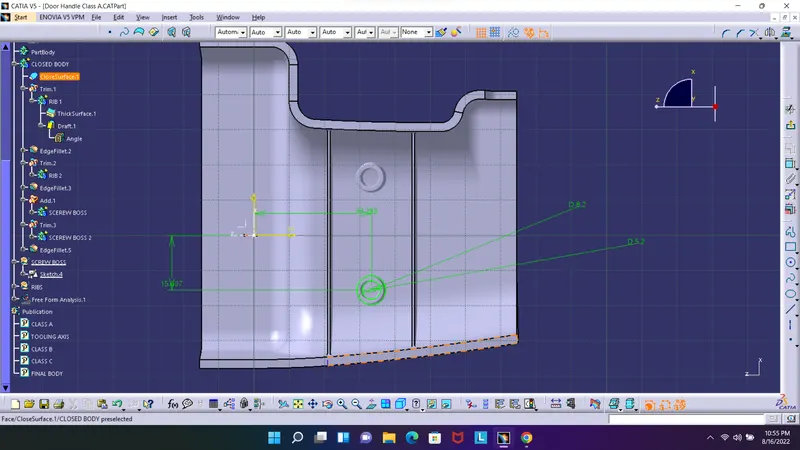
Screw boss round are created by dimension and second screw boss created by transalate
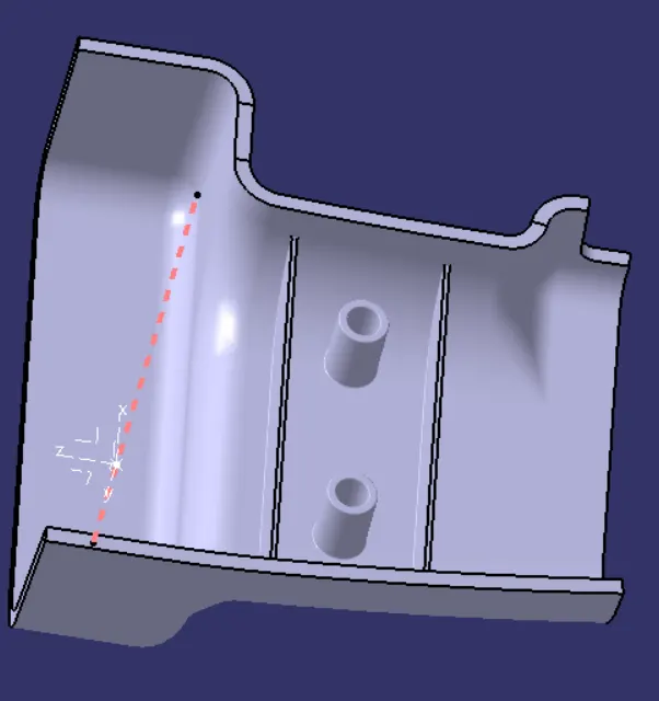
FINAL DRAFT ANALYSIS ON BODY , RIBS AND SCREW BOSS
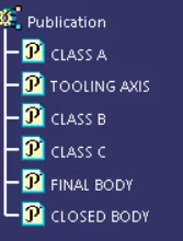
PUBLICATION
CONCLUSION:
- The Tooling axis and the SolidCAT part with B Side Features is created from the given Class A Surface and Draft Analysis is Performed