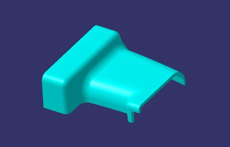
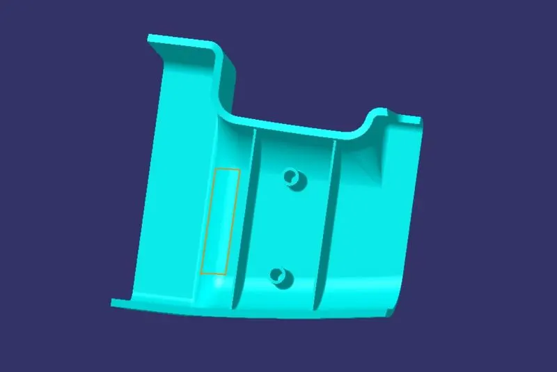
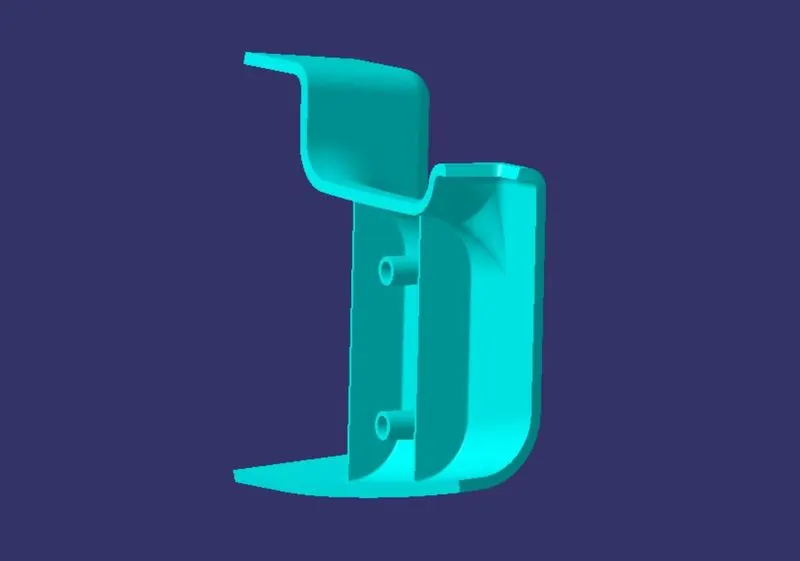
Week 9 - Attachment Feature Creation (Ribs & Screw Boss) - Challenge 1
Create the rib for the Drill Handle considering the design rules mentioned in the video.
AIM:
- To Create the Door Handle Component from the given Class-A surface.
- To Create the tooling axis for the given Class-A Surface meeting the requirements of the draft angle.
- Creating class B surface by using offset command.
- Fixing class B offset surface making into a single part.
- to create a class C surface with a class A surface as a reference.
- To perform the Draft analysis on the model.
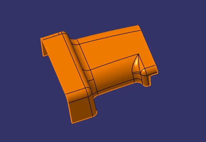
CLASS A SURFACE
Class A surface is shown below for better visual clarity.
TOOLING AXIS CREATED WITH THE REFERENCE OF CLASS A SURFACE
The Tooling Direction is basically the direction that the mold pulls a part. The mold is built in two separate pieces, basically. You have a Cavity side and you have the Core side. The Core pulls apart from the Cavity and that's the Dye line or the Tooling Direction.
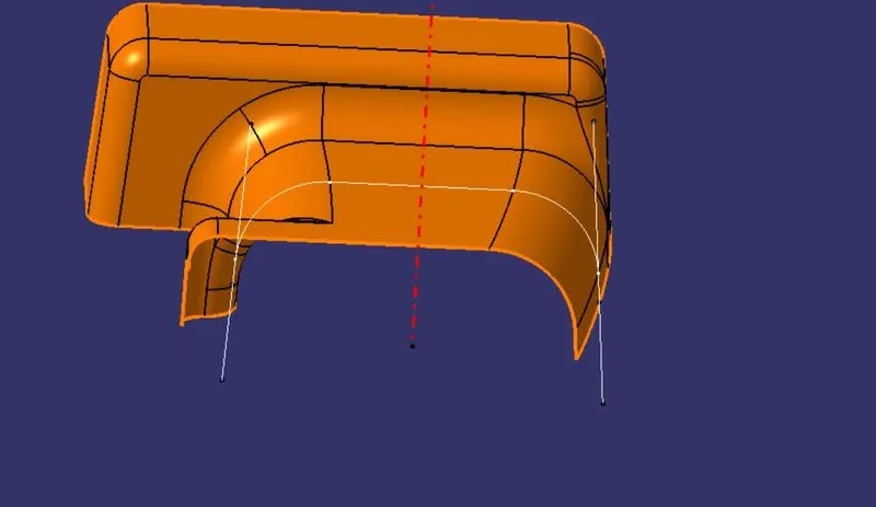
- Display the cad part and check for any gap.
- using intersection command creating intersection in top of the surface.
- the line has been drawn for both the end
- BISECTING LINES were used to get the exact medium from the two sides so that maximum positive draft angle can be achieved.
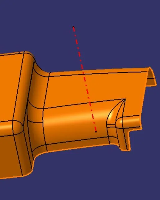
Creation of Class B:
- Now for Class B creation, we have extracted surfaces from Class A and untrimmed them to obtain the original parent surface.
- These surfaces are then offset to the required thickness.
- After offsetting, all the surfaces are trimmed into the required shape.
- Required fillets are given to the surfaces.
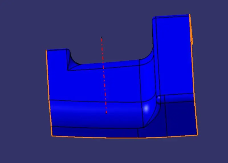
Class A & B surface shown to geather
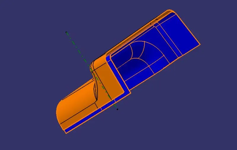
C class surface :
Class C Surface has swept along the boundary CLASS A surface with respect to the tooling axis direction with a draft angle of a maximum 3 degrees minimum of 0.5 degrees.
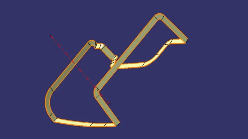
number of sweep command is used to create this class c surface
class c was created with the help of a sweep
and show bellow
also, encure that class c should be pass 3 degrees of draft angle
complete A, B, AND C are shown in the join
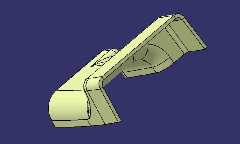
some image is shown below for a clear understanding of how the component is looks.
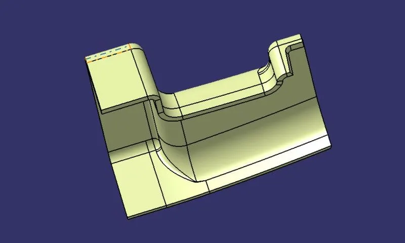
Draft analysis :
The Draft Analysis allows the user to easily analyze a part for a proper draft angle. A Draft Angle describes the amount of taper for molded or cast parts perpendicular to the parting line. Find the Draft Analysis in the Tools tab. Draft Analysis is applicable for 3D part models.
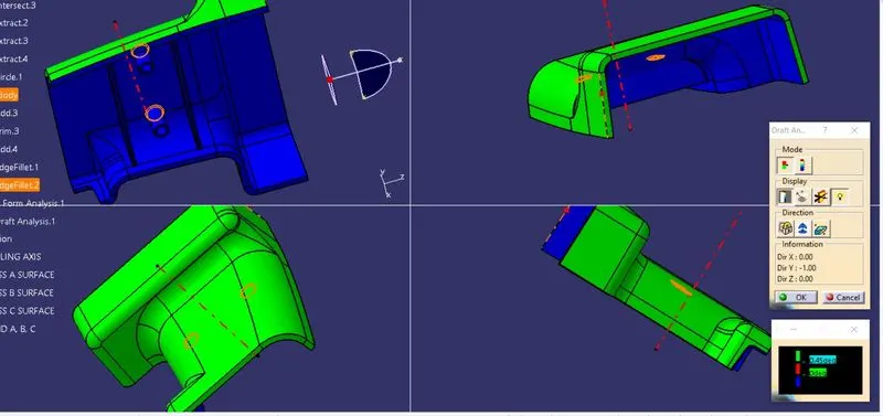
The draft analysis button within CATIA V5 will help you quickly gather the draft angle on multiple surfaces without the need for tedious manual measurements. Here is a quick rundown of how the icon works when you have a given die direction.
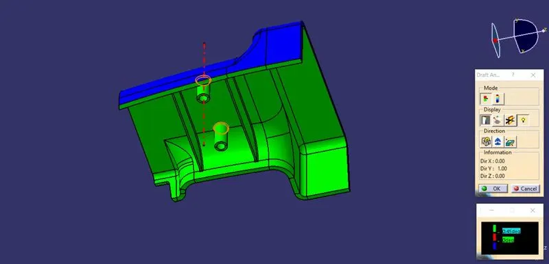
- Before going to drat analysis go to customized view parameter >under mesh >check material and then click ok.
- Now for draft analyses go to insert » analysis » feature draft analysis.
- Use the compass to define the draft direction.
- In the color, the scale changes the draft angle to 3 degrees.
- The component changes to green as an indication of the passing draft angle.
- Use a running point to check the angle on the component.
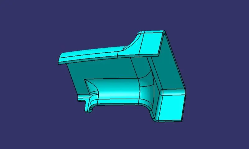
CLOSED BODY IS SHOWN BELLOW
CREATING THE RIB
Ribs are thin wall protrusions that extend perpendicularly from a wall or plane. They are usually found in clusters offering support to a plane that would have otherwise been too thick, but can also be stand-alone support for a single wall. They are commonly used to provide additional support and strength to a part. Thickness and location are essential to rib design.
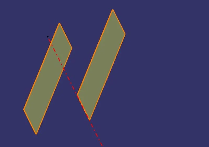
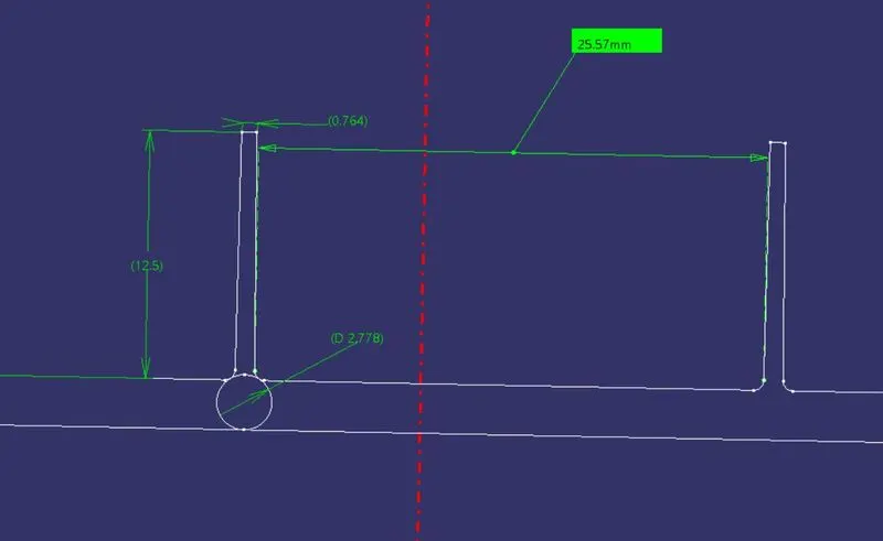
Next, the profile is extruded, to find the height,h=Wall thickness * 5
=2.5*5
= 12.5 mm
Therefore, the height is 12.5 mm
The extruded surface is thickened,
Thickness,w=0.4*t
=0.4 2.5
=1mm
Therefore, the thickness of the rib is 1 mm
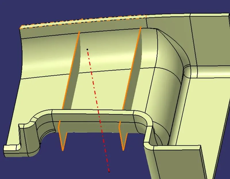
2D dimension has been shown bellow
CREATING THE SCREW BOSS
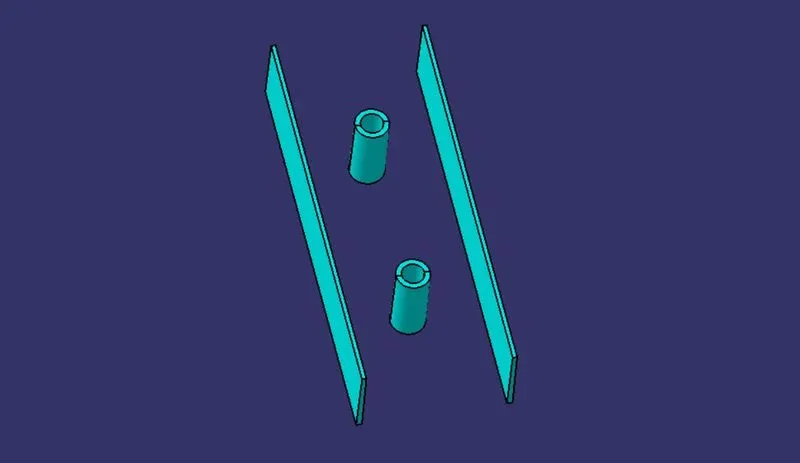
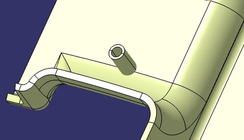
Screw Boss features are commonly found in injection molding designs. They are used to aid in the assembly of molded parts by providing a channel for a screw. Their primary use is to strengthen holes or slots in the surface present in the part model.
Design rules consider while creating a screw boss
• Thickness
• Draft
• optional radii
• Boss gussets
• Type of ejection
The construction process of creating the screw boss is explained below:
For thickness, the design rule is as follows,
Thickness,w=0.6*T
=0.6*2.5
=1.5 mm
Therefore, the thickness of the boss can be 1.5 mm per side.
In this case, we have considered the size of the screw boss as M06.
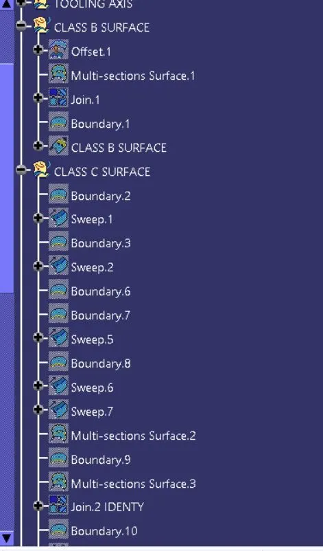
Tree Structure
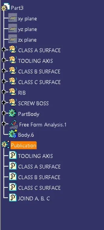
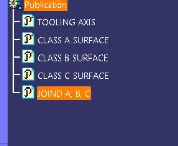
the publication is shown bellow
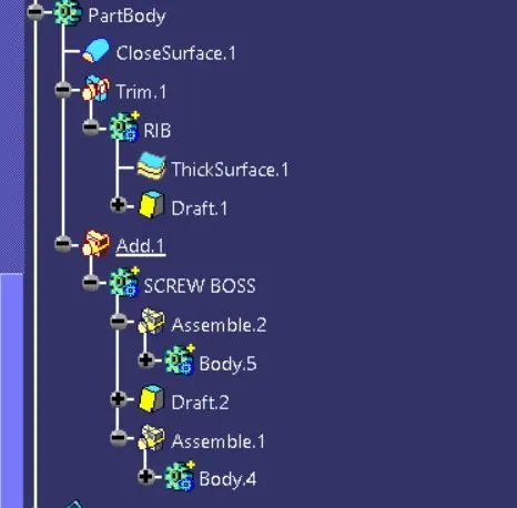
part body image is shown bellow
Screenshots of the completed design in various orientations (Isometric, Front, Side, and Top View)