Week 9 - Attachment Feature Creation (Ribs & Screw Boss) - Challenge 1
AIM:
- To Create the Door Handle Component from the given Class-A surface.
- To Create the tooling axis for the given Class-A Surface meeting the requirements of the draft angle.
- To Attach B side Features in the component.
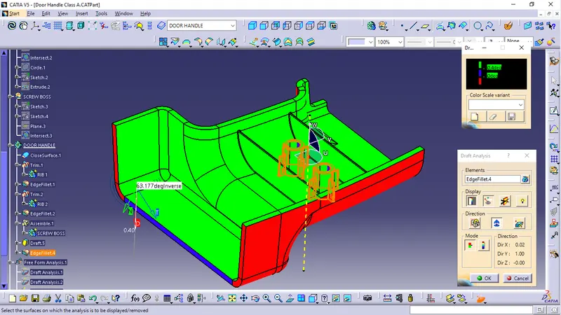
- To perform the Draft analysis on the model.
DESCRIPTION:
1. CREATING TOOLING AXIS -
The Tooling Direction is basically the direction that the mold pulls a part. The mold is built in two separate pieces, basically. You have a Cavity side and you have the Core side. The Core pulls apart from the Cavity and that's the Dye line or the Tooling Direction.
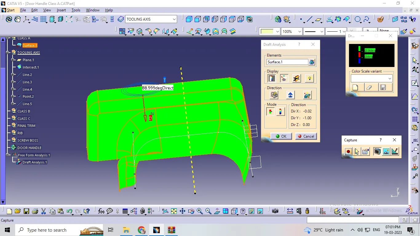
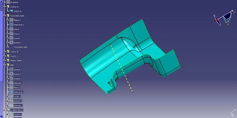
here first we required tooling axis for draft analysis. tooling axis is works as provided to direction for injection moulding as well as direction of draft angle where is check it right or wrong so 1st we extract the surface of class A and than create point on it use this point we create the line by using line command for proper direction which want to the draft analysis and this line knows as the tooling axis.
B surface :
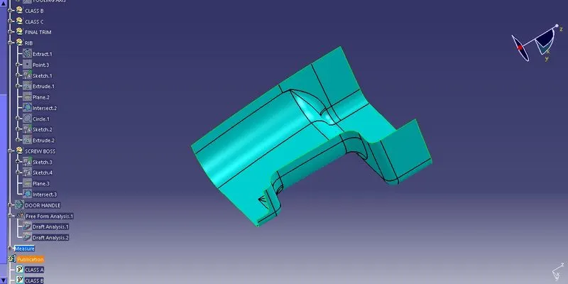
here we just offset the Class A surface and get the B surface body here we offeset the 2.5mm value so we get the thickness is 2.5mm is mention in above so we offset the A surface for 2.5mm
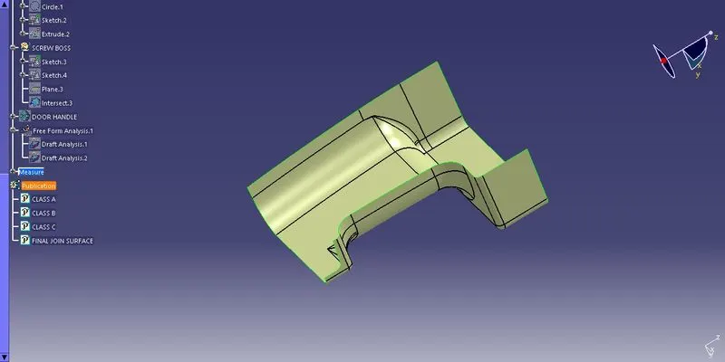
C surface :
c surface creation by using the sweep command so 1st we create a boundary than disassemble get two curve 1st out-side surfaces than second is in-side surfaces after that we used sweep commat in that goto draft section on choose surface reference option and sweep it similar think done inner curve than we get c surface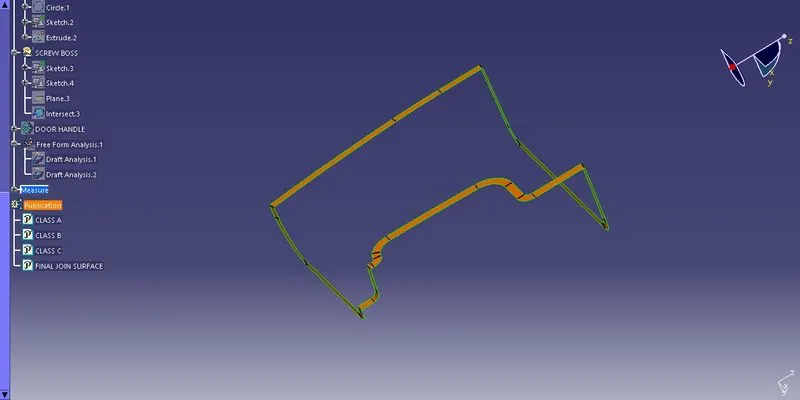
Close Surface :
close surface get the by trim final surface of c class shown in above image with the b class surface in that we required condition to properly trim it so we used exploer command and exploer B surface required dimension same think done both inner and outer curve than trim it get close surface
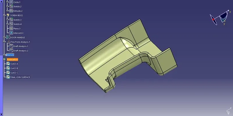
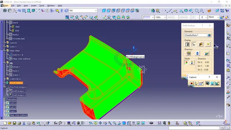
Procedure of Draft Analysis :
here we goto the draft ananlysis and 1stly we required direction so used tooling axis so we drag the compass and properly mounting on tooling axis than fix it after that goto analysis and get the results
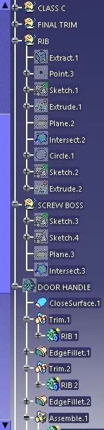
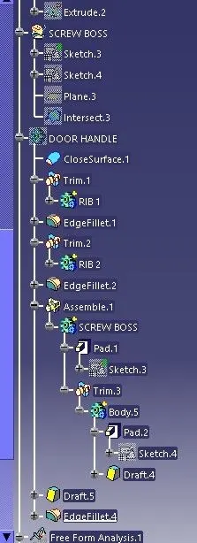
Rib Creation
Ribs are a feature in plastic injection molded parts. They are thin extensions that run perpendicular from a wall or plane. They are commonly used to provide additional support and strength to a part. Thickness and location are essential to rib design.
Proper Rib Design involves five main factors:
- Thickness
- Hieght
- Location
- Quantity
- Manufacturability
- Design Principle for Rib Creation
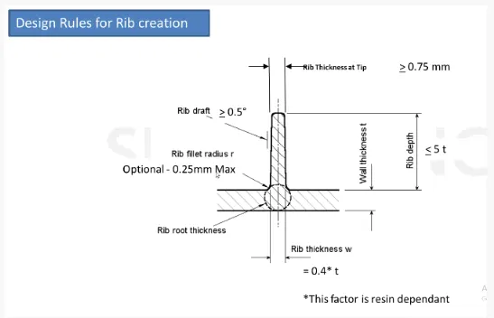
Sketch used for rib creation
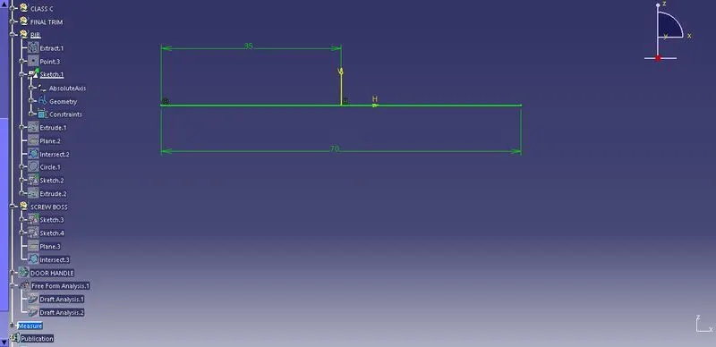
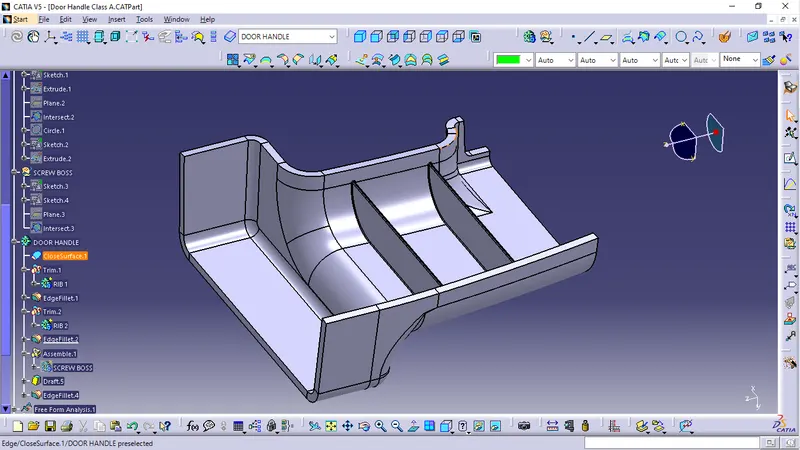
Rib design
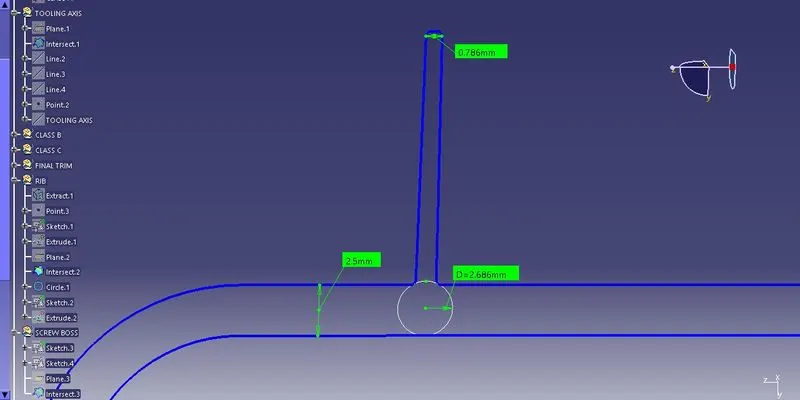
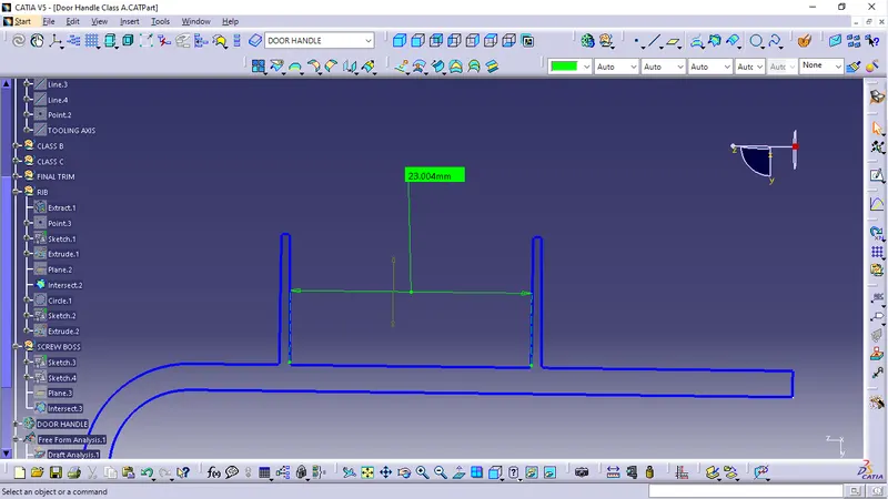
Screw boss design
- Design Principle for Screw Boss Creation
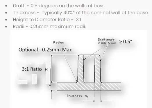
In plastic parts, bosses are typically used to assist in assembly, as a receptacle for a screw or threaded insert or as the locator for a mating pin on another part. Because of its function, a boss must have sufficient strength to do its job. This dictates a minimum size for the feature.
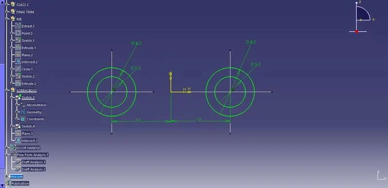
Sketch used for screw boss design
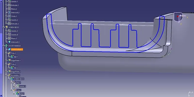
Screw boss
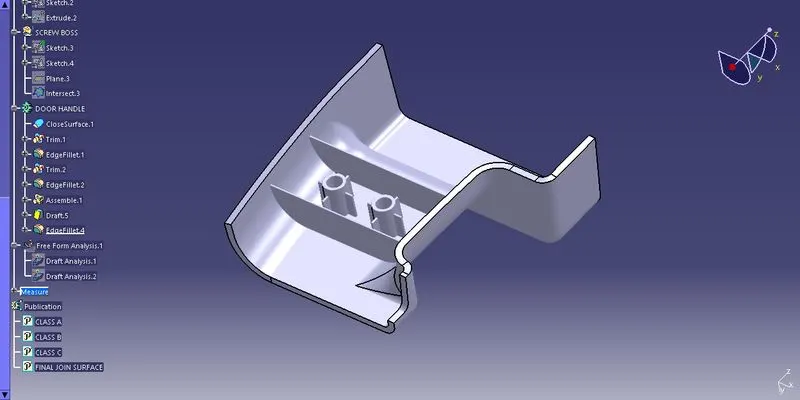
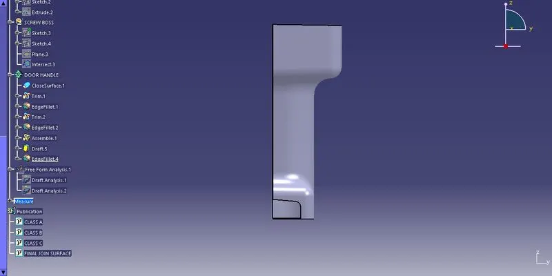
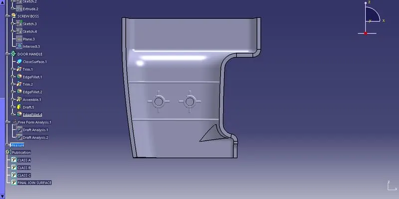
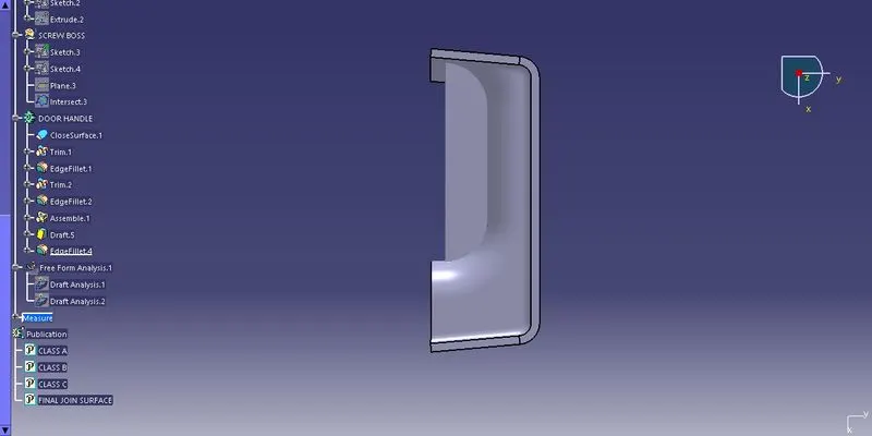
Final model Images
- Screenshots of the completed design in various orientations (Isometric, Front, Side, and Top View)
Final draft