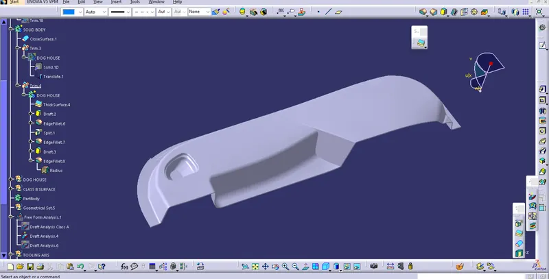
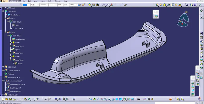
Week 9 - Attachment Feature Creation - Challenge 2
Week 9 - Attachment Feature Creation - Challenge 2
Aim- Create the Dog House for the Door Trim considering the design rules mentioned in the video. Consider the thickness of the part to be 2.5 mm.
Procedure to be followed-
- Creating the Tooling Axis
- Draft analysis of Class A surface
- Creating Class B surface
- Creating Class C surface
- Creating Solid body
- Creating Engineering features Dog house
- Draft Analysis of the Dog house
- Draft analysis of Solid body with engineering features.
Creating the Tooling Axis
- Tooling axis: The opening of the cavity, core, or mould is determined by the tooling axis. You can first check the connectivity of the supplied Class A surface by using the Boundary or Join feature to see and fix the surface's open edges.
- Next, decide visually which plane or surface the tooling axis should be on. We must extract the surface, mark a point, and then create the intersection in order to identify the tooling axis. To determine the tooling axis, draw a line at the intersection's edge and create a bisecting line.
Class A surface is done using computer-aided industrial design applications. Class A surface modellers are also called "digital sculptors" in the industry. We recieve the class A surface as the input from the class A modlers.
- the below image shows the class A surface with the tooling axis.
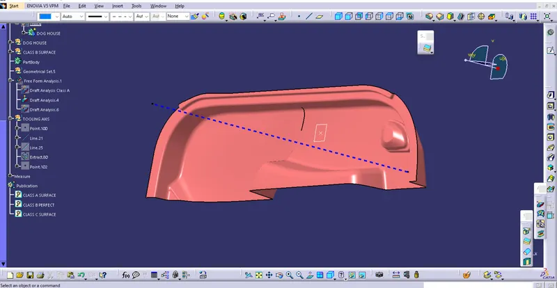
Draft analysis of Class A surface
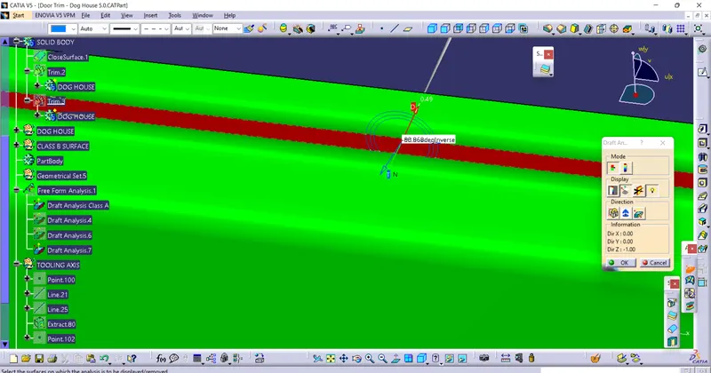
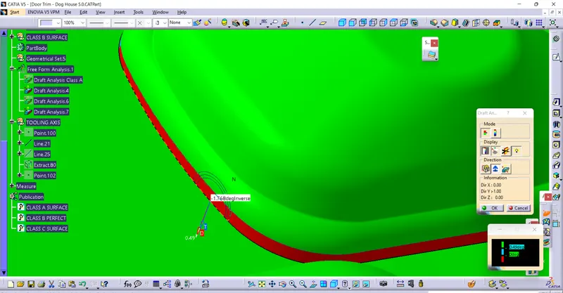
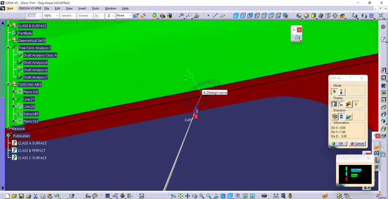
- We must verify that the input we received is appropriate. In draught analysis and tooling guidance, a surface must be clear; if not, we must provide feedback to the class. To create the necessary draught for the particular surface, a designer
- the below image showing red colour in some parts of class A which is not cleared in the draft anlysis so we need the inform the class A deigner to provide minimal draft to it.
Creating Class B surface
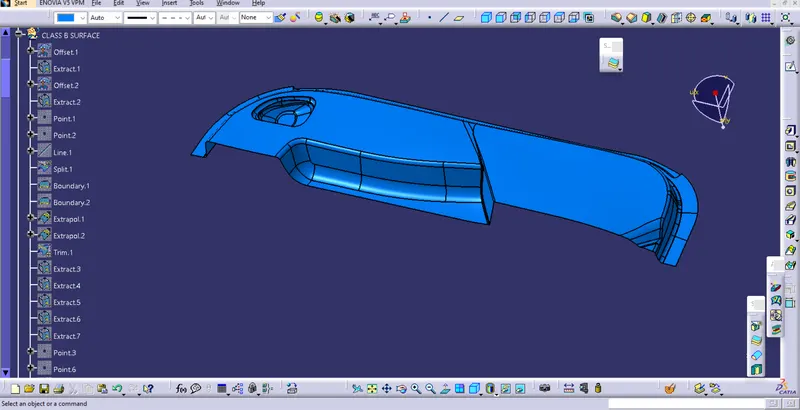
- To create the class B surface, we need to offset the surface of Class A. here we have given the offset value of 2.5 mm as per requirement. After giving offset we can se the some of the surface is not filled such as the portion of the fillets we need to fill those patches by multi section surface and some by extracting and trimming it.
Below image shows the class B surface
Creating Class C surface
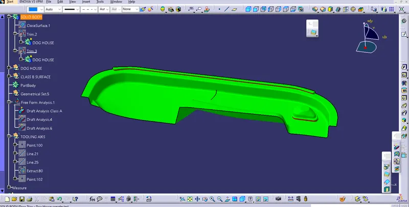
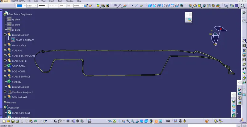
- Class A and Class B surfaces are connected by a Class C surface. The sweep command generates a Class C surface. We can generate a class C surface by using the sweep command to create the boundary of a class A surface at a 93 degree angle (Profile type: Line, Subtype: with reference surface).
- After creating the C surface, we must combine the A and C surfaces before trimming them with the B surfaces.
The below image shows the class C surface
Creating Solid body
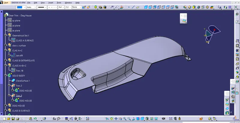
- We must choose the close surface option in the part workbench in order to build the solid body of the surface.
Creating Engineering features Dog house-
Dog hosue is used in automobile to connect the one component with another for example if we want to connect bumper with the garnish the dog house can be use and most import characterise of dog house is it prevent sink mark on the class A surface.
Rules for crating dog house.
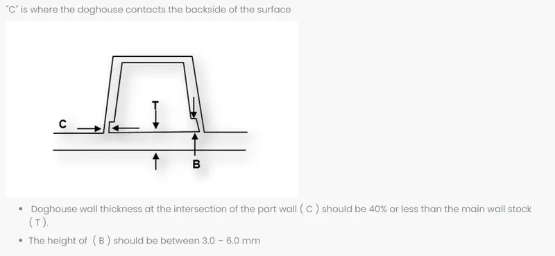
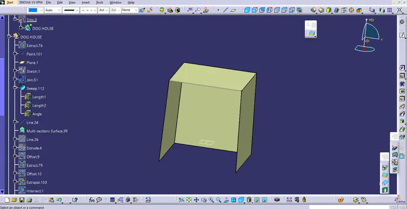
To create the dog hosue we need to create a point and a plate create the sketch and sweep it the direction of toolig axis provding the draft angle of 0.5 degree. provide thikness of 2 mm . once created we need to ceate the side core and split from the solid body.
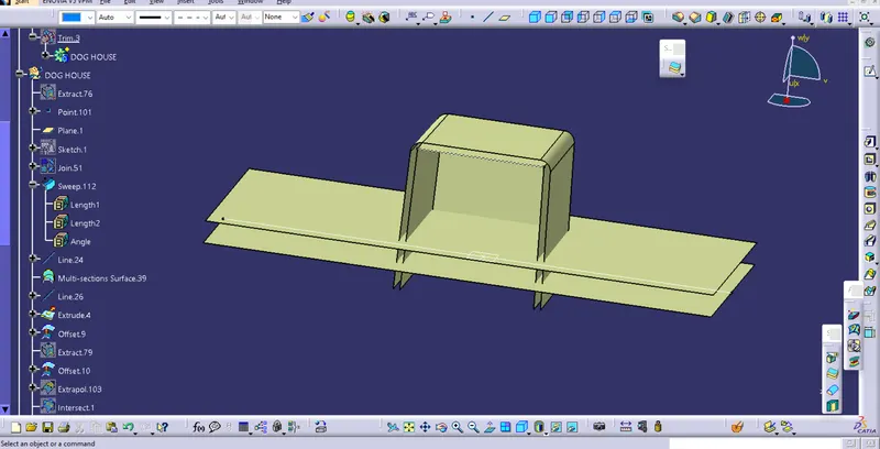
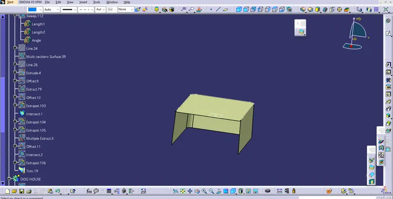
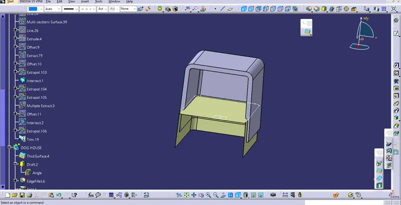
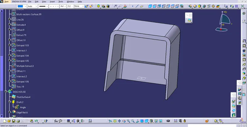
Draft analysis of Dog house
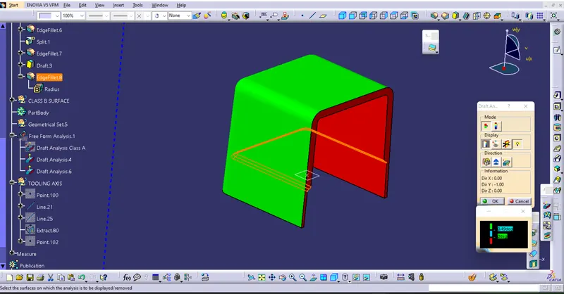
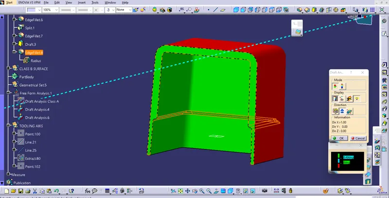
Initially, we need to check the draft analysis concerning the tooling axis and then concerning the side core axis.
Tooling axis-
In the colour bar, I gave 0.49 deg for green because the sweep angle is 0.5 deg for the outer surface.
Side core Axis-
In the colour bar, I gave 0.49 deg for green because the sweep angle is 0.5 deg for the outer surface
Draft Analysis of the solid body-
I utilised the included draft analysis tool in the generative shape design workbench to conduct the draft analysis for the solid component body with the dog home feature. I first set the compass to point at the tooling axis, then I chose the solid component body and entered a 3 degree draft angle in the colour bar. Some faces aren't clearing properly even if I give the colour bar a draft angle of less than 2 degrees because of the class A surface's curves and draught angle. Then i reduce the draaft angle to 0.49 degree many of the portion is been clered som of the C surface was not cleared in the draft because the c surface neede to draft with reference to tooling axis.
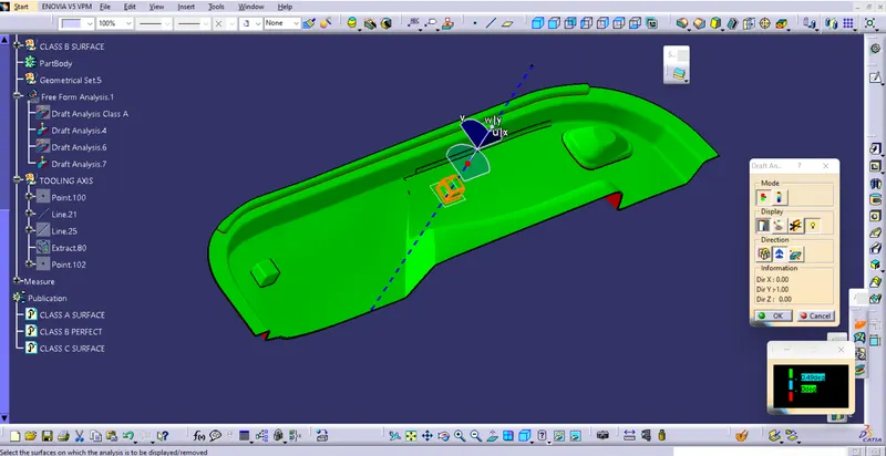
Door trim with the dog house