Week 9 - Attachment Feature Creation - Challenge 2
CLASS A SURFACE:-
In Automotive design, a Class A Surface in any of a set of freeform surfaces of high efficiency and quality. Although, strictly, its nothing kore than saying the surfaces have curvature and tangency alignment- to ideal aesthetical reflection quality.
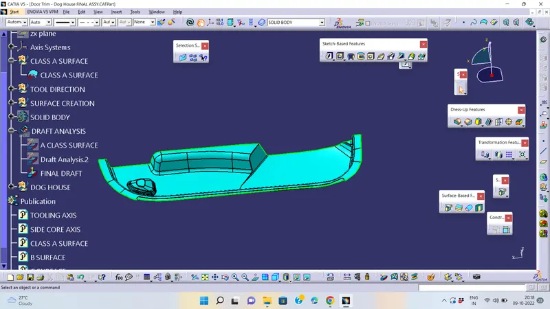
TOOLING AXIS CREATION:-
Tooling axis is which side to perform core and cavity direction to finding easily when a take a any surface to extract and create point on that surface and take a line that point (point-direction) select required direction.
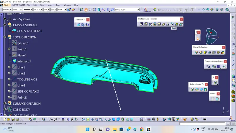
Draft Analysis of Solid Model:-
Draft analysis of the solid part as in Class A Surface
The Draft Analysis command enables you to detect if the part you drafted will be easily removed. This type of analysis is performed based on color ranges identifying zones on the analyzed element where the deviation from the draft direction at any point, corresponds to specified values.
- Before going to drat analysis go to customized view parameter >under mesh >check material and then click ok.
- Now for draft analyses go to insert » analysis » feature draft analysis.
- Use the compasss to define the draft direction.
- In the colour scale change the draft angle to 1.45degree.
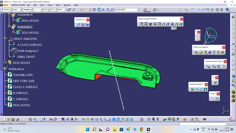
- The component changes to green in indication of passing draft angle.
- Use running point to check the angle on the component.
Importance of Draft:-
By accounting for thermoplastic shrinkage during the cooling process, draft angles significantly reduce friction between the finished, cooled part and the side of the mould, Not only does this create a much easier release process, but it also offers several other benefits, depending on the design of the part which is as follows:
• Reduces the chance of damage to the part due to friction during the release.
• Reduces wear and tear and chances of damage to the mould.
• Ensures a uniform, smooth, unscratched finish when required. • Ensures the integrity and uniformity of other surface finishes and textures.
• Reduces overall cooling time by lessening or eliminating the need for unconventional ejection setups.
• Most, if not all, of these benefits, offer either direct or indirect overall production cost reductions.
B SURFACE CREATION:-
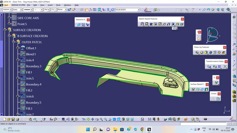
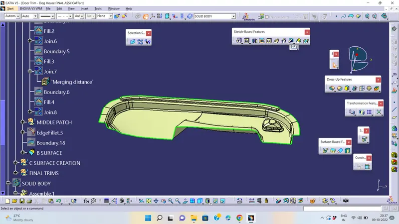
- Extract the surfaces from the class A using multiple extract and untrim them.
- Use Extrapolate to make sure that all the untrims are properly intersected to trim and offset the surfaces to 2.5 mm to create the thickness.
- Trim the extra surfaces using trim command.
- Insert them into new geometrical set and name it with respective part names.
C SURFACE CREATION:-
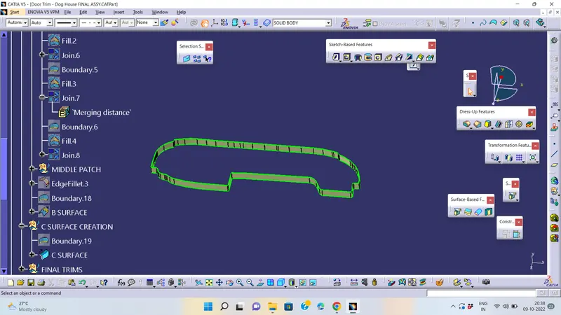
- Extract the boundary from the class A surface using boundary command.
- Using disassemble tool to divide the boundary as the boundary contains domains.
- Use sweep command to produce c surface
- by using boundary and surface with respect to angle 3 degree or 93 degree
Joining Class A,B and C Surfaces to get a Closed Surface:-
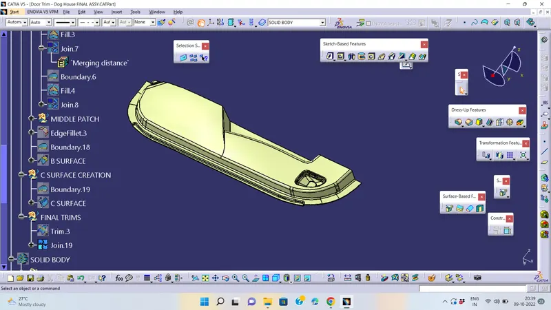
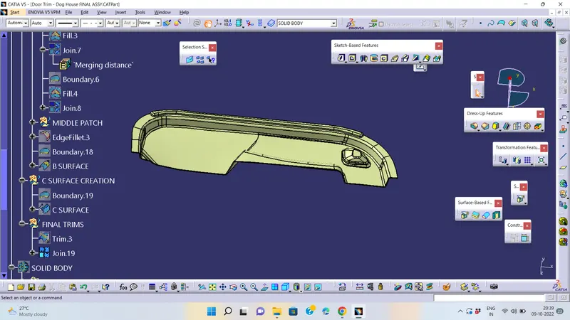
SOLID CONVERTION OF SURFACE BODY
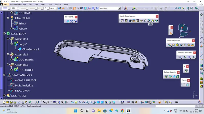
B SIDE FEATURE CREATION
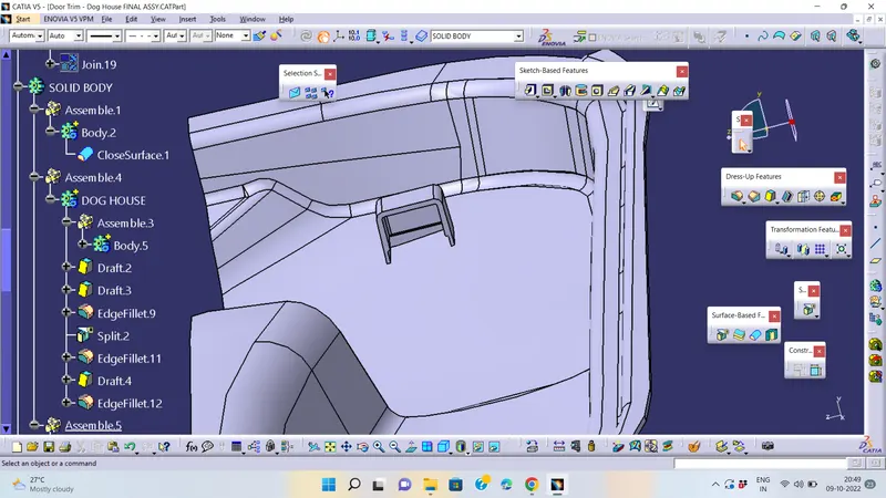
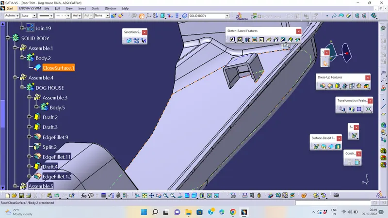
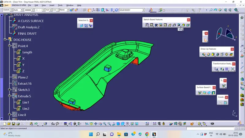
DOG HOUSE:-
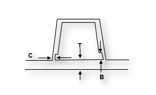
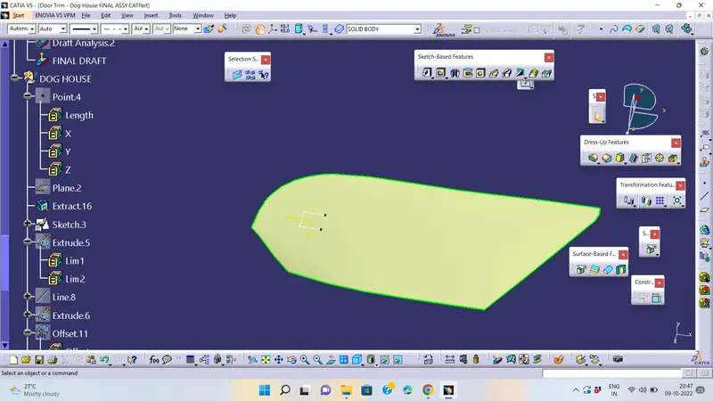
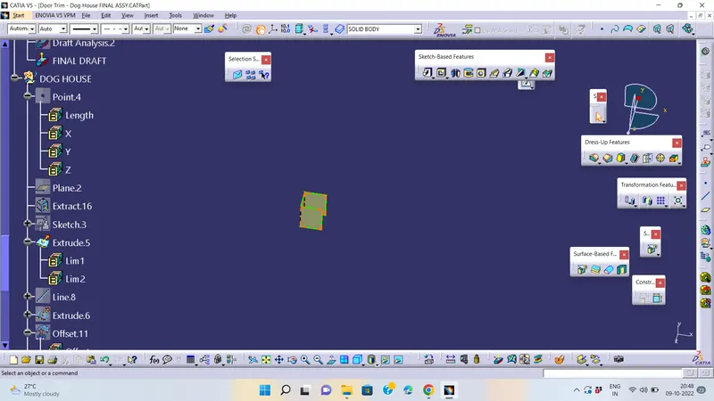
Create the Dog House as per the design rules and give the requiredd draft angle.
- Dog House wall thickness at intersecton of the part Wall(C) should be 40% or less than the main wall stock(T).
- Height of (B) should be between 3-6 mm.
DRAFT ANALYSIS:-
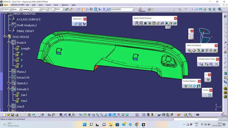
go to insert< analysis< draft analysis and follow usual procedure to do the analysis.
Align the compass and click on the surface and as expected the model is mostly in red color i.e. negative draft with respect to the axis. whenever draft analysis is mainly for find the designed part should be produceble or any difficulty will be faced in manufacturing plants
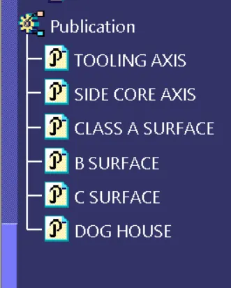
PUBLICATIONS:-