Week 9 - Attachment Feature Creation - Challenge 2
AIM:
To create the Screw Bosses for the Centre console coin holder considering the design rules by using Catia V5.
OBJECTIVE:
- Create a tooling axis following the OEM standard
- Making the Rib According to design rules
- Part Thickness : 40% NOMINAL VALUE and Draft angle : 0.5 Deg
- Performing the draft analysis to the component
INTRODUCTION:
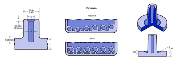
Assembly of molded parts by providing a channel for a screw. Designing plastic screw bosses is fairly straightforward but there are a few considerations to ensure a strong connection between parts and mitigate cosmetic defects. ince screws are going into a hole without threads, plastic will be displaced as you thread the screw into the boss. This is when a counterbore comes in handy. A counterbore is additional space designed into the part to accommodate this excess material.
Screw bosses can be reinforced with ribs or gussets for added strength and durability. As we mentioned above, a boss should not be next to exterior walls, but you can use coring ribs to keep it connected to the part’s exterior wall without risking sink.
Materials. Softer, less brittle materials work best for molded parts that need to accept screws. If your part is polycarbonate, for example, consider blending it with ABS.
Design Rules for Screw Boss Creation:
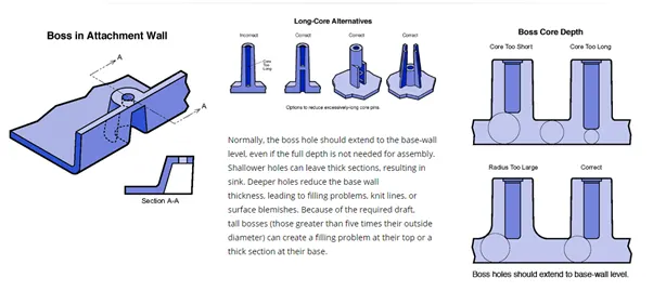
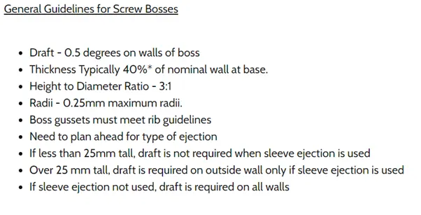
METHODOLGY:
- Creating the Tooling Axis
The tooling direction is used to find the direction in which the part is removed from the core and cavity. The draft angle should be positive to the tooling axis to manufacture the component easily. The step by step procedure of creating the tooling axis is given below.
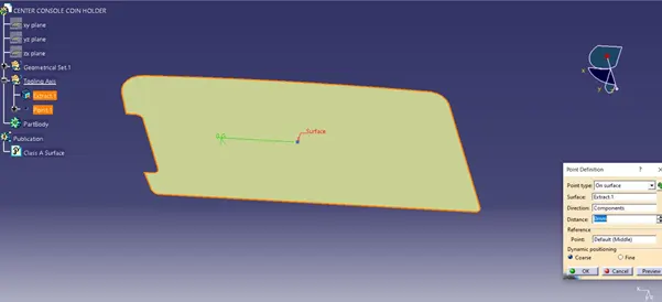
Step: 1
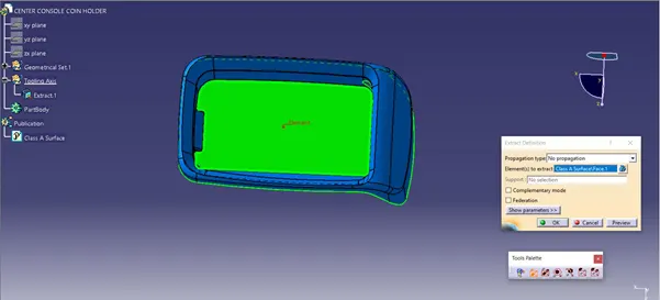
Creating the point on surfaces respectively also extract the surface of the component.
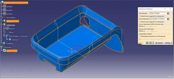
Step: 2
Now creating the intersection to the Z-Y and Z-X direction of the surface as shown below.
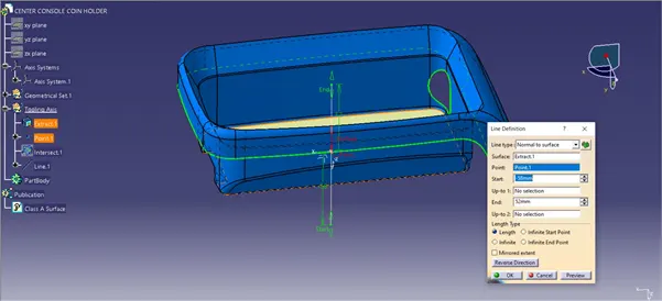
Step: 3
It is symmetry and normal surface, hence we can directly by zero distance value based to normal to the surface.
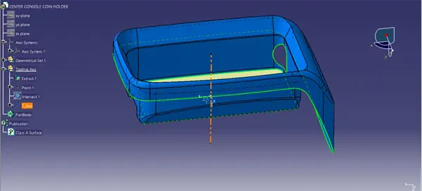
Finally we get our main tooling axis for the door arm rest component.
- Creating the Screw Boss on the Coin holder:
Step: 1
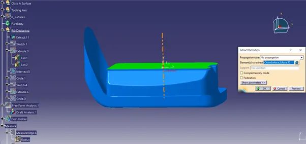
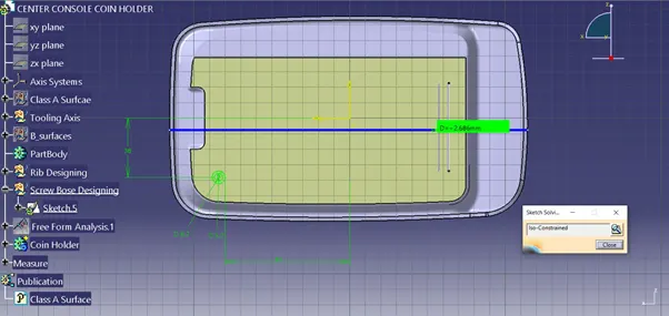
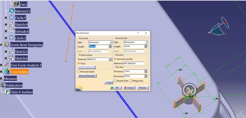
Creating the sketch by extracting the class A surface, by each surfaces separately, point and axis system created simultaneously on the surface. Using positioned sketch making as shown below.
Step: 2
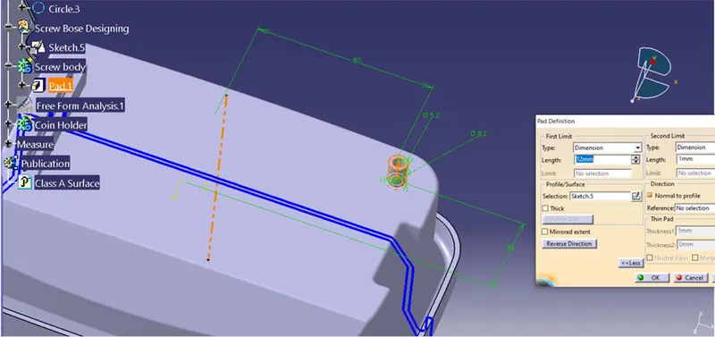
The sketch extruded to surface for minimal distance from the extract of coin holder as shown below.
Step: 3
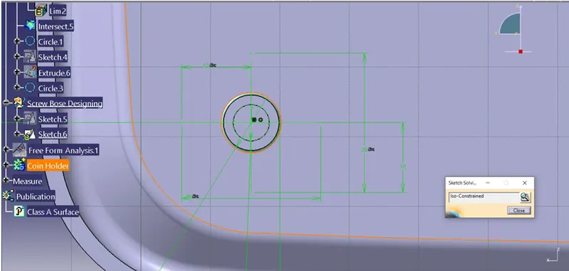
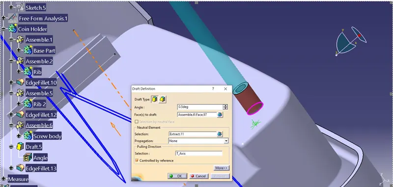
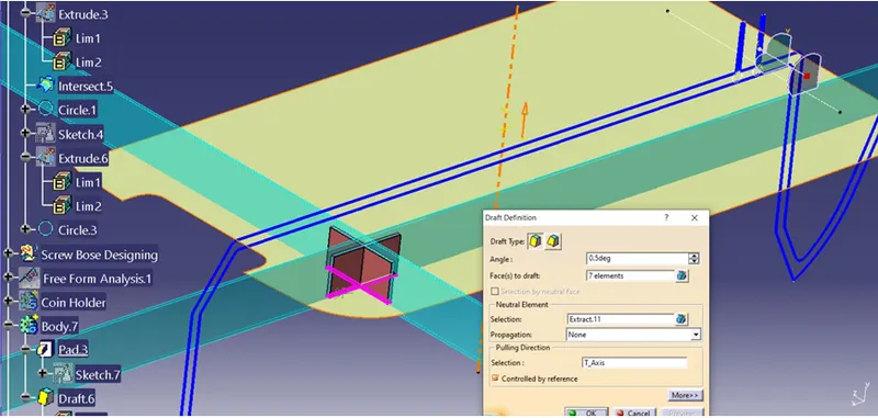
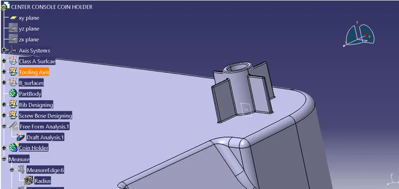
The rib has been created by same procedure by sketch and extruding for supporting the screw boss and it is drafted for 0.5 deg.
Step: 4
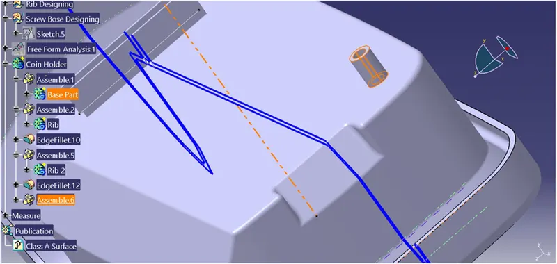
It is assembled to main body and it is filleted for radius 0.25 of smooth edges as shown below.
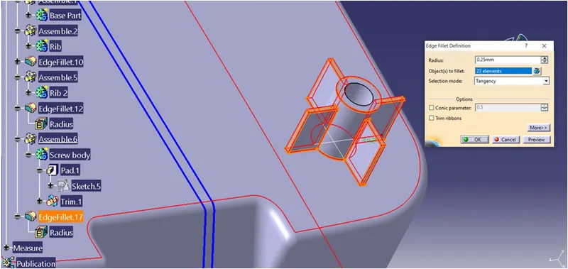
Step: 5
Analysing the Rib root thickness for the coin holder rib by creating intersection for the model as shown below.
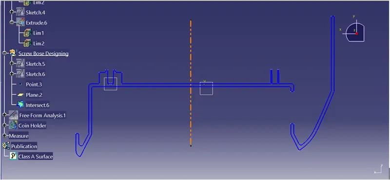
Finally we have created Screw boss with rib supported to the coin holder has shown below.
- Performing Draft Analysis:
The Draft Analysis command enables you to detect if the part you drafted will be easily removed. This type of analysis is performed based on colour ranges identifying zones on the analysed component where the deviation from the draft direction at any point, corresponds to specified values. This rule of thumb applies to parts with mold depths of up to 2 inches. At this size, draft as low as 1½ degrees will allow for an easy, non-damaging release from the mold when the expected shrinkage of the thermoplastic material occurs.
It’s also important to remember that draft angles are just one component of an effectively designed injection molded piece. Design for manufacture is one of the easiest ways to improve the quality and efficiency of your injection molding process, and it never hurts to stay up to speed on all injection molding best practices.
- Draft Analysis for Screw Boss formation:
Step: 1
First we have to set the compass on the main tooling axis to get the direction of core and part moves along as shown below.
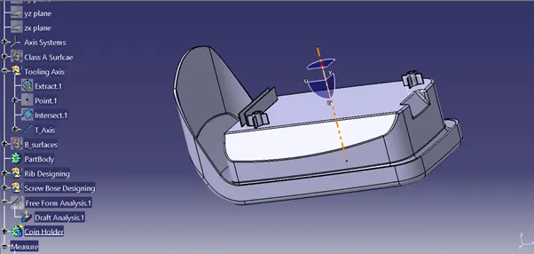
Step: 2
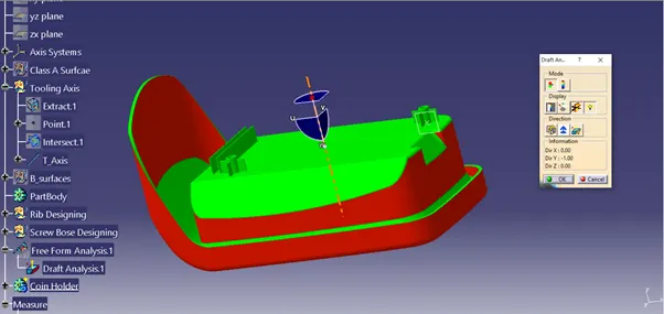
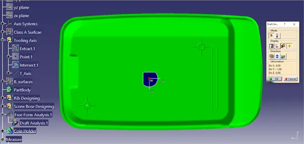
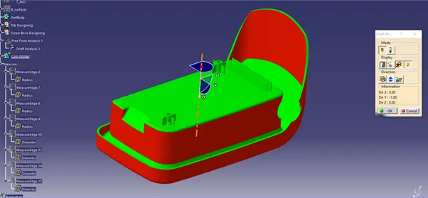
Once compass is locked in the axis, directly click on the surface it will appear quality of draft surface whether, it is pass or failed. Here the draft angle is given as 0.5 degree. Hence we achieved green colour on top surface. Hence it accepts the draft angle for the surface, so we build good quality component.
Step: 3
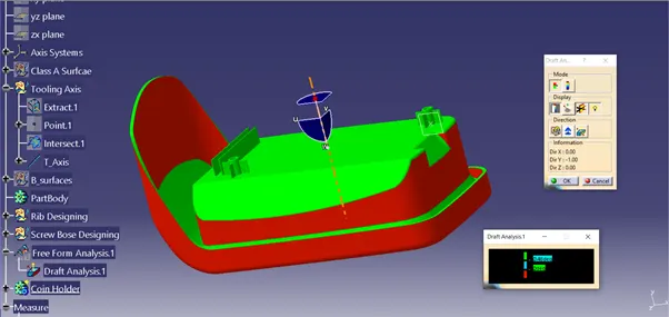
Now we check colour variant scale to ensure the maximum and minimum area draft angle is achieved by displaying by green, red and blue colour respectively. If the surface appears red in colour while analysing it is not accepted.
Step: 4
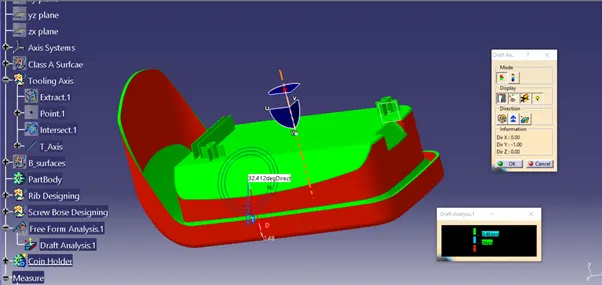
We can check the angle of draft given to surface by using draft tool analysis just point the over the surface where we have check angle of given draft to the component as shown below.
Screenshot views of coin holder with draft analysis:
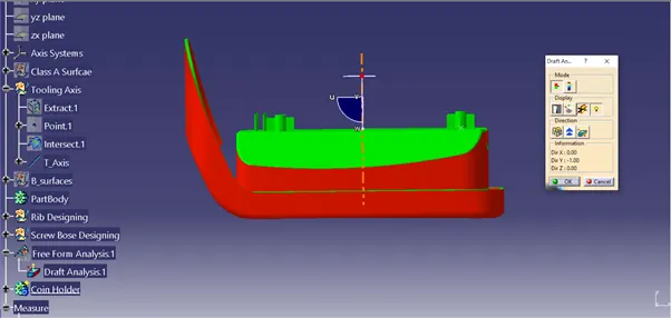
Front View:
Top View:
Isometric View:
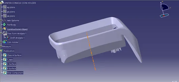
Publication:
Conclusion:
Creation of the Screw Boss on coin holder has been successful done by guidance of design rule. It has been converted from surface into solid body. The tooling axis has been created according the OEM standard. Drafting Analysis has been performed and results has been updated in step by step methodology.
Challenge: 2
AIM:
To create the Dog House for the Centre console coin holder considering the design rules by using Catia V5.
OBJECTIVE:
- Create a tooling axis following the OEM standard
- Making the Rib According to design rules
- Part Thickness : 40% NOMINAL VALUE and Draft angle : 0.5 Deg
- Performing the draft analysis to the component
INTRODUCTION:
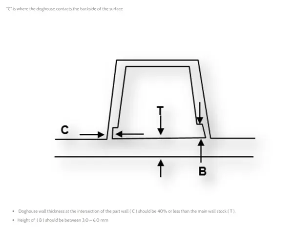
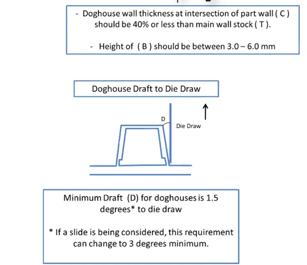
Dog house is an engineering feature used in plastic trim design. Dog houses are used as supporting feature. Sometimes other engineering features like snaps; locators etc. are mounded on them to increase their strength. Dog houses are subjected to draft analysis to prevent breakage of the component during ejection from mould cavity. Dog house and other engineering components are built on B-surface.
Design Rules for Dog House Creation:
METHODOLGY:
- Creating the Tooling Axis
The tooling direction is used to find the direction in which the part is removed from the core and cavity. The draft angle should be positive to the tooling axis to manufacture the component easily. The step by step procedure of creating the tooling axis is given below.
Step: 1
Creating the point on surfaces respectively also extract the surface of the component.
Step: 2
Now creating the intersection to the Z-Y and Z-X direction of the surface as shown below.
Step: 3
It is symmetry and normal surface, hence we can directly by zero distance value based to normal to the surface.
Finally we get our main tooling axis for the door arm rest component.
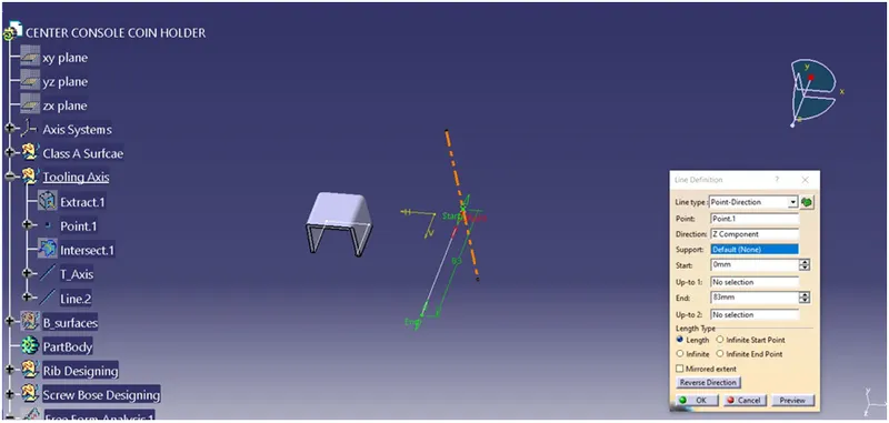
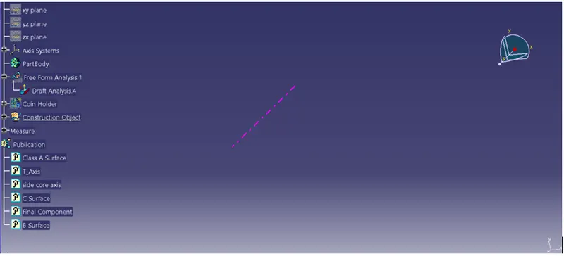
- Sliding Tooling Axis:
To analyse the dog house, the slider core tooling axis is need it done creating point to line definition to the z axis as shown below.
- Creating the Dog Boss on the Coin holder:
Step: 1
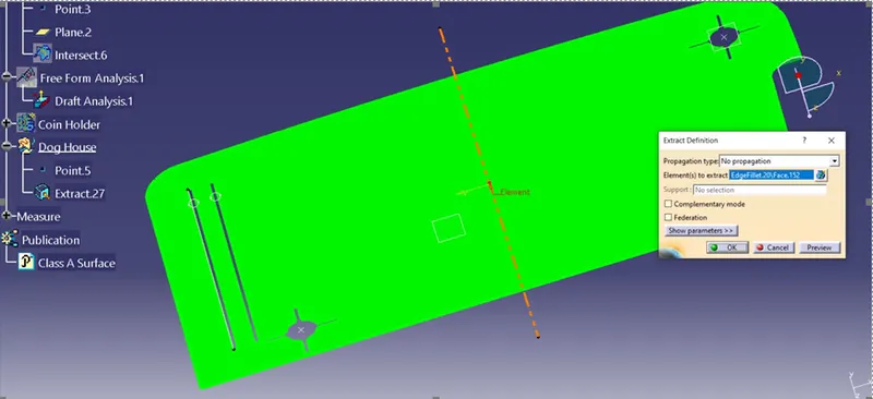
Creating the sketch by extracting the class A surface, by each surfaces separately, point and axis system created simultaneously on the surface. Using positioned sketch making as shown below.
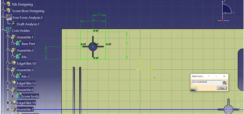
Step: 2
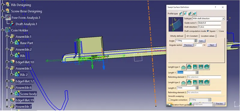
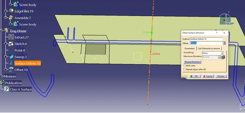
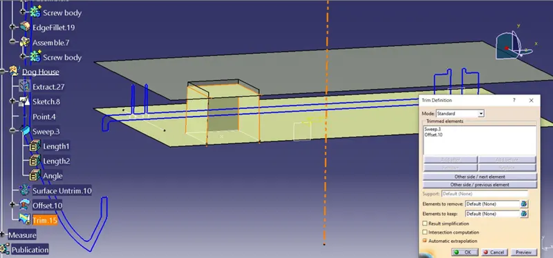
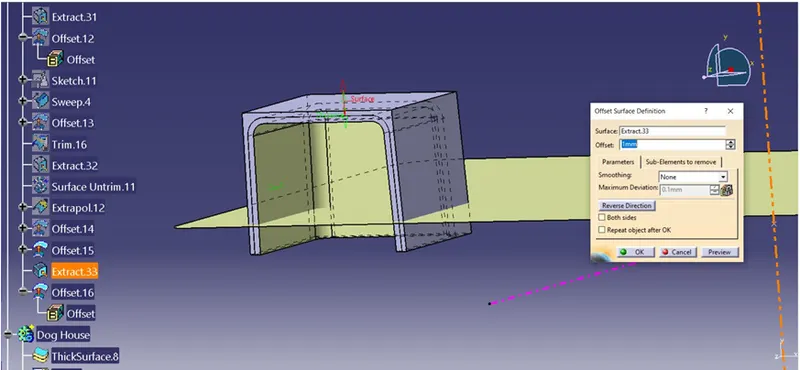
The sketch extruded by using sweep option for tooling axis direction from the extract of coin holder or 1.5 deg angle as shown below, the extract surface from Class A has been offset to make top surface of dog house by trimming it.
Step: 3
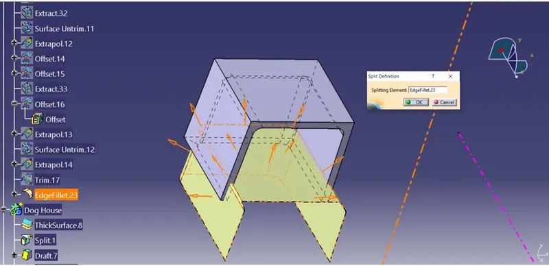
The sweep surface is converted into solid by thicking the surface for 2mm and it is extrapolated.
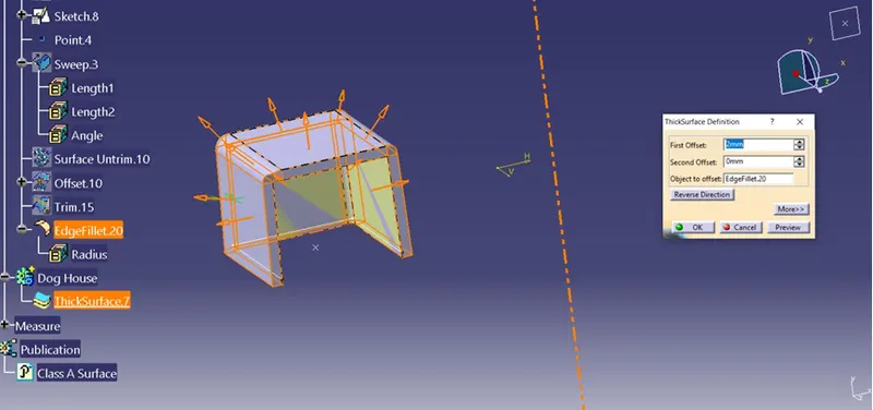
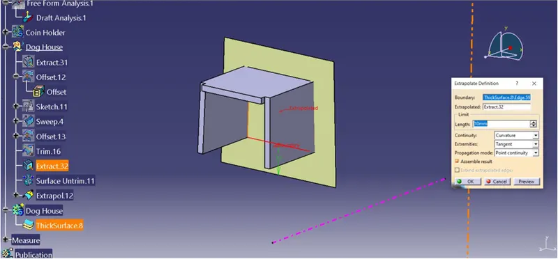
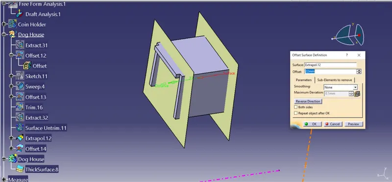
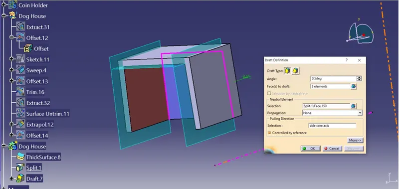
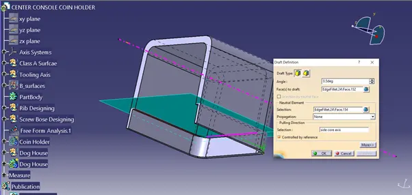
To crate the draft, first we have to extract inner wall surface and it is offset to 2.5mm to make the trim as shown below. The draft angle is 0.5 mm for the dof house.
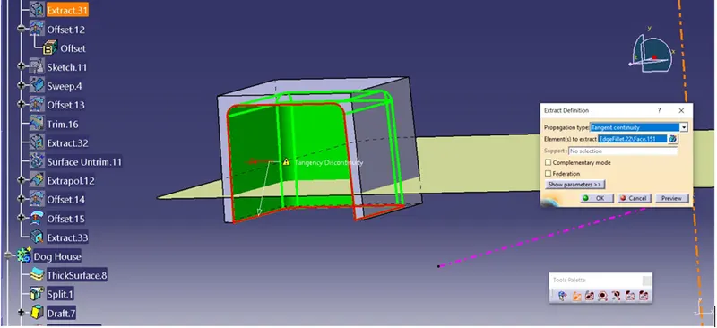
Step: 4
The undercut has been made by extrapolated surface and it is offset to the minimal value and it is trimmed to get perfect under cut.
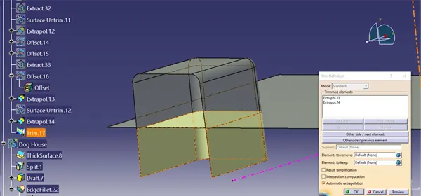
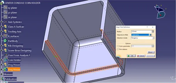
To get the proper clearance for removal of the component is drafted for 0.5 at the undercut area and it is filleted for 0.5 mm as shown below.
Step: 5
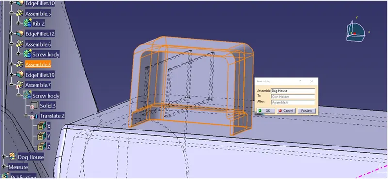
It is assembled to main body and it is filleted for radius 0.25 of smooth edges as shown below.
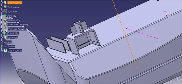
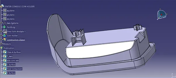
Finally we have created Dog house to the coin holder has shown below.
- Performing Draft Analysis:
The Draft Analysis command enables you to detect if the part you drafted will be easily removed. This type of analysis is performed based on colour ranges identifying zones on the analysed component where the deviation from the draft direction at any point, corresponds to specified values. This rule of thumb applies to parts with mold depths of up to 2 inches. At this size, draft as low as 1½ degrees will allow for an easy, non-damaging release from the mold when the expected shrinkage of the thermoplastic material occurs.
It’s also important to remember that draft angles are just one component of an effectively designed injection molded piece. Design for manufacture is one of the easiest ways to improve the quality and efficiency of your injection molding process, and it never hurts to stay up to speed on all injection molding best practices.
- Draft Analysis for Dog House formation:
Step: 1
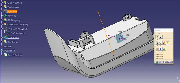
First we have to set the compass on the main tooling axis to get the direction of core and part moves along as shown below.
Step: 2
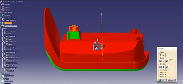
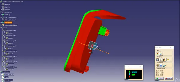
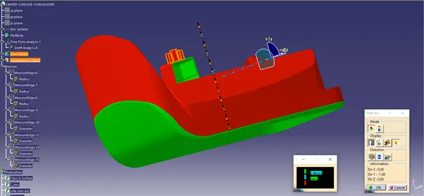
Once compass is locked in the axis, directly click on the surface it will appear quality of draft surface whether, it is pass or failed. Here the draft angle is given as 0.5 degree. Hence we achieved green colour on top surface. Hence it accepts the draft angle for the surface, so we build good quality component.
Step: 3
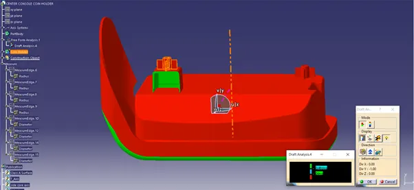
Now we check colour variant scale to ensure the maximum and minimum area draft angle is achieved by displaying by green, red and blue colour respectively. If the surface appears red in colour while analysing it is not accepted.
Step: 4
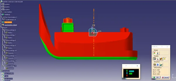
We can check the angle of draft given to surface by using draft tool analysis just point the over the surface where we have check angle of given draft to the component as shown below.
Screenshot views of coin holder with draft analysis:
Front View:
Top View:
Isometric View:
Publication:
Conclusion:
Creation of the Dog House on coin holder has been successful done by guidance of design rule. It has been converted from surface into solid body. The tooling axis has been created according the OEM standard. Drafting Analysis has been performed and results has been updated in step by step methodology.