Challenge 7 : Concept Modelling of Steering Wheel
- Title of the Project:
Development of Steering wheel of car using Alias Auto Studio
- Objective
To build the steering wheel of the car using the Curves traced from the given blueprint of the model.
- Introduction
Surface modelling is the art of building complex geometrical features, one surface at a time. Usually surface modelling is used to create flowing, organic shapes, so the patch meeting between surfaces are more important.
We describe the 'smoothness' of a junction, where one surface meets another, the term ‘G’ stands for “Geometry”. The more alike the surfaces flow must be more smoothly the adjoining surfaces.
- Design methodology / approach :
A design approach for modelling this steering wheel has been briefly explained below using flow chart.
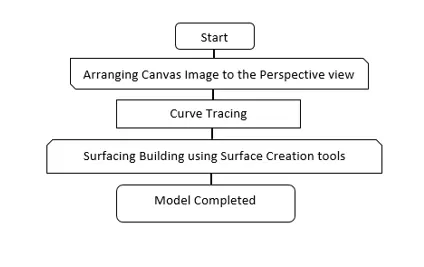
5. Description of Modelling:
Concept modelling is done by various methodology, here we have blue print of the steering wheel. It’s easier to develop the model by tracing out the curves of the steering wheel by curve generate options. Once the curve networking is done, we pour the surfaces to curve which gives volume to your model.
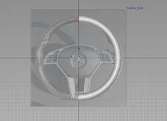
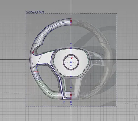
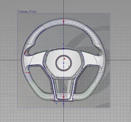
In the working layout we are going to import the canvas image proportionally as shown below in the figure.
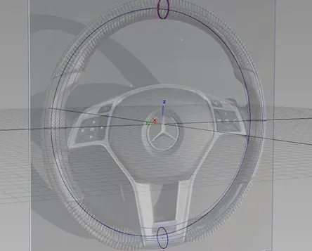
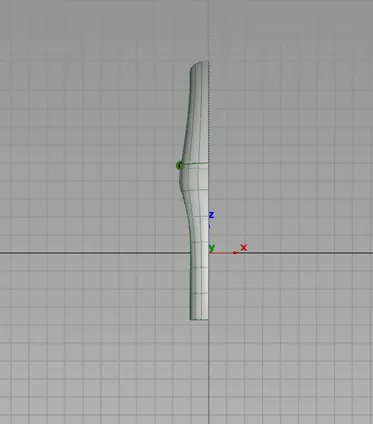
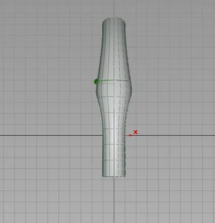
Once the canvas images arranged according to the view, curve tracing has been initiated by using the key point curve tool with maximum 5 degree curve. This curves are arranged according to the shape of given blue print by the stretching CV hulls in all proportion view to build as 3D object.
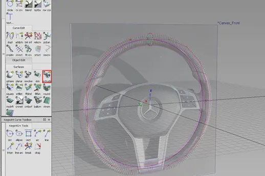
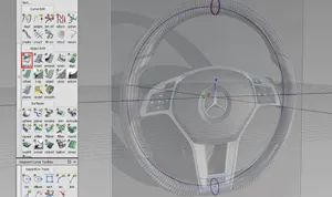
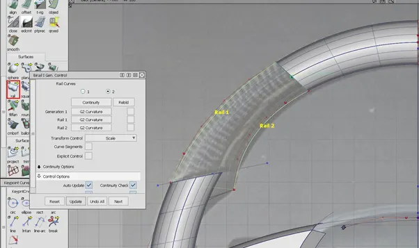
The upper part of patch is constructed by align the curve to flow by G2 curvature continuity to get the surface flow over the edge curve as shown below.
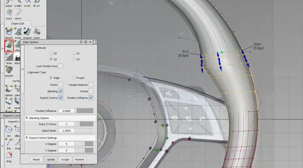
Once complete surface generated, the sharp edges are smoothened to get required surface low over the edges are done by using surface fillet option. In the fillet the edges of two surface are smoothed by Chord type of G2 curvature as shown below.
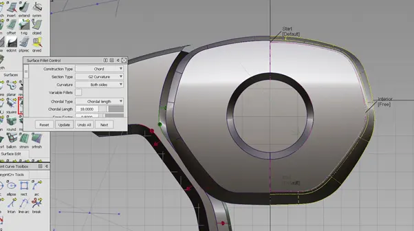
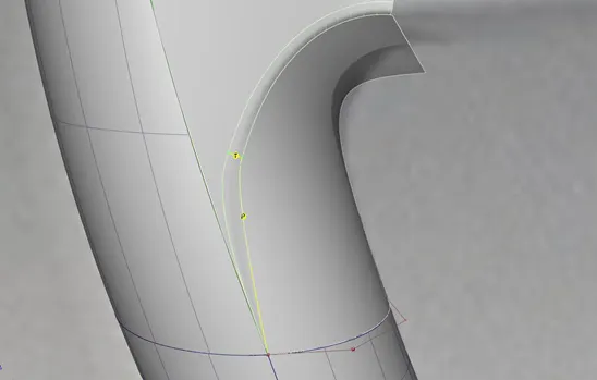
At the meeting point of two fillet edges are so complex to make smooth surface it is trimmed and align according the required shape. It is filled by using the Free form blend to achieve the closed surface area.
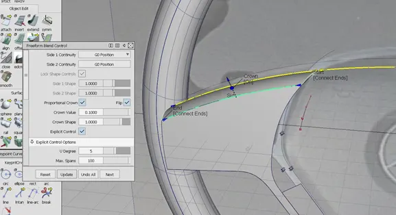
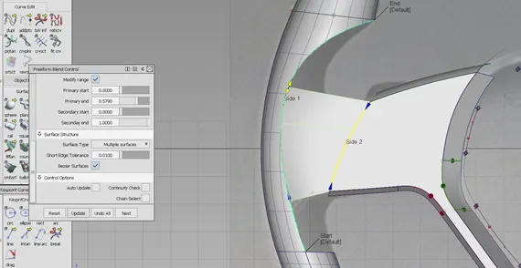
Once half of the part of steering wheel is completed it is duplicated to required axis to get full completed steering wheel, by using symmetric option.
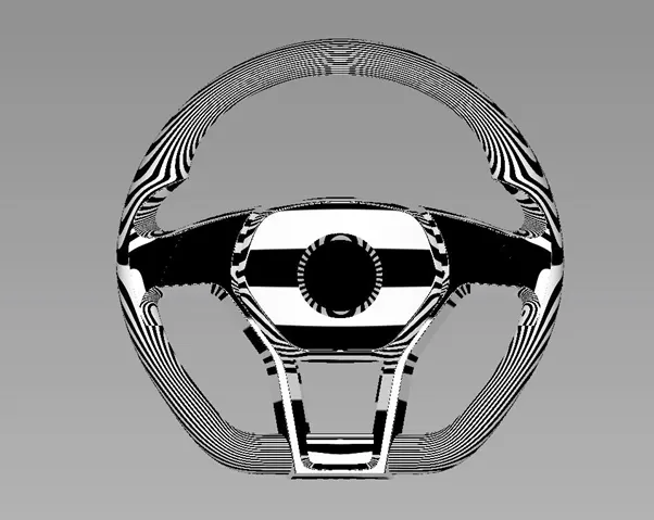
Finally achieved the surface flow continuity of the steering wheel and it is shown by Zebra line highlighted as shown below.
6. Screenshots of Model in the report.
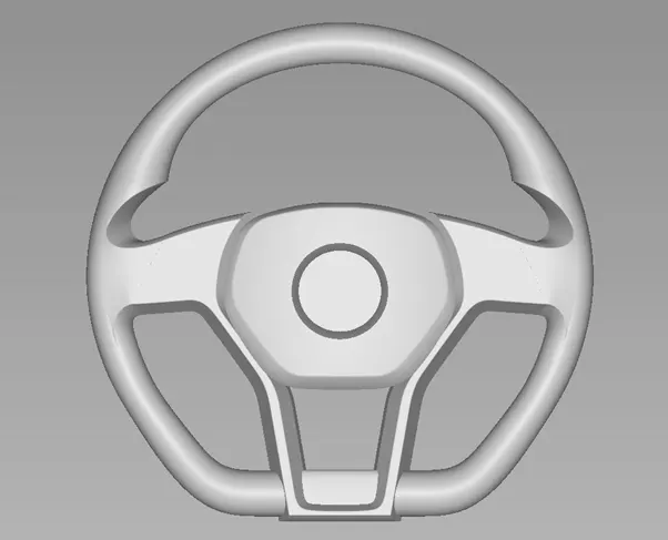
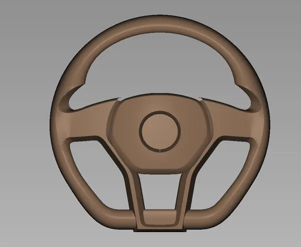
Front View of the Steering wheel
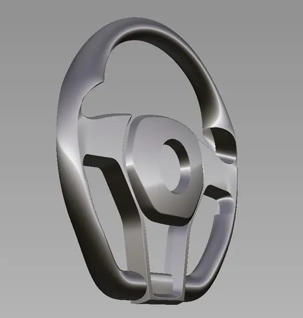
Side View of the steering wheel
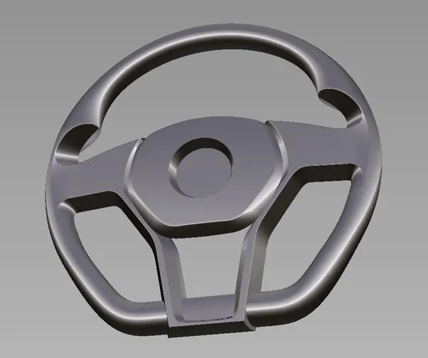
Isometric View of the Steering wheel
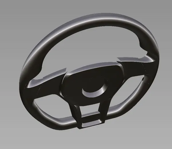
Clay Model Shade of the fender
7. Conclusion
Modelling of steering wheel has been developed successfully by using Curve networking and Surface volume. It has been built by using the Blue print of the steering wheel, it is shaped according to the proportion in perspective manner. Modelling strategy of the fender has been discussed briefly with feature used to make surface volume in the pictorial representation.